
CNC Data Into Industrial Edge Applications: What the Floor Actually Needs
Edge computing only helps when the data arrives clean and the box survives the coolant and chips around it. This page covers the signal path from controller to edge node, and the machined parts that path depends on.
In this article
- 1
- 2
- 3
- 4
- 5
- 6
- 7
What matters before you buy hardware
Why CNC Data Into Industrial Edge Applications Starts at the Controller
Most CNC controllers were never designed to publish data. Fanuc, Siemens, Heidenhain, and Mitsubishi each expose a different set of variables, and many of them are locked behind an option or a licensed function. The first decision is what you are allowed to read, not what you want to read. On older machines this often means a digital I/O tap for cycle signals and nothing else.
Once you know the available tags, decide the sampling window. Cycle counts, spindle hours, and alarm states change on the order of seconds. Axis position, spindle load, and feed override change on the order of milliseconds. Mixing them into one stream at one rate wastes bandwidth and hides the fast events you actually care about.
A practical pattern is two tiers. A slow tier at 1 Hz carries state, counts, and program numbers. A fast tier at 1–10 kHz carries vibration, current, and position, but only when a trigger condition is met. The trigger might be a spindle load threshold or a specific M-code. Everything else stays out of the pipe.
The gateway sits between these tiers and the network. It reads the controller, timestamps locally, and publishes northbound. Timestamping on the machine matters more than most teams expect. If two cells log the same event 200 ms apart because their clocks drifted, root-cause work gets expensive fast.
- 1Read-only firstNever write back to a production controller until the read path is stable for weeks.
- 2Two sampling tiersSlow state at 1 Hz, fast events on trigger, not continuously.
- 3Local timestampsNTP or PTP at the gateway, not at the historian.
Choosing the Link Between Machine and Edge Node
Ethernet is the default now, but the physical layer is where projects stall. A shop floor with VFDs, servo drives, and induction heaters is an electrically loud place. Unshielded Cat5 run alongside motor cables will drop packets, and dropped packets look exactly like machine downtime in the dashboard.
Use shielded cable with the shield bonded at one end only. Keep the run under 90 m for copper. Above that, go fiber. Media converters are cheap compared to a week of intermittent faults that nobody can reproduce.
For machines with only serial or fieldbus available, a protocol converter at the machine is the standard answer. PROFIBUS, Modbus RTU, and CANopen all convert cleanly. The converter should be DIN-rail mounted inside a sealed box, not zip-tied to a cable tray.
Wireless is tempting for retrofits. It works when the access point is dedicated to that traffic and the latency budget is loose. It does not work for closed-loop control or for anything with a hard cycle-time requirement. Treat wireless as monitoring only.
- 1Shield bonded one endPrevents ground loops while still draining induced noise.
- 2Fiber above 90 mCheaper than chasing intermittent link faults.
The Enclosure Is a Machined Part, Not a Box
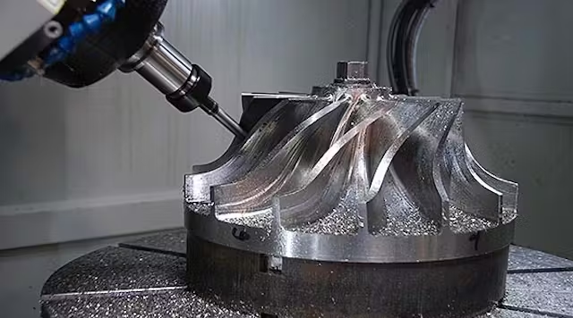
An edge node on a CNC machine sees coolant mist, cast iron dust, and vibration. A sheet metal box with a foam gasket will pass IP54 on day one and fail by month six. The sealing face is the part that matters, and it needs to be machined flat, not folded.
Gasket grooves are usually cut to 1.5–2.0 mm width and 1.0–1.5 mm depth for a standard O-ring cord. Depth tolerance drives compression, and compression drives seal life. A groove held to ±0.05 mm gives a consistent squeeze; a folded flange does not.
Cable glands are the second failure point. Each gland needs a machined boss with a flat face and a thread that matches the gland's IP rating. Mixing a IP68 gland into an IP54 wall does not upgrade the assembly. The weakest interface sets the rating.
For washdown areas, 316L stainless with a bead blast finish holds up better than anodized aluminium. Anodizing is fine for general machine-tool environments, but caustic washdown chemicals attack the oxide layer over time. Hardcoat anodizing is a middle option when weight matters.
- 1Machined sealing faceFlatness under 0.05 mm across the gasket land.
- 2Gland boss per glandOne flat, threaded boss for each cable entry.
- 3316L for washdownAnodized aluminium for dry machine-tool areas.
Heat, Vibration, and Where the Node Actually Sits
A fanless x86 node running at 15 W inside a sealed IP67 box will cook itself. Thermal design starts with the enclosure, not the CPU. A machined aluminium body can act as the heatsink if the internal mounting bosses are tied to the wall with enough contact area.
Rule of thumb: 20 cm² of external surface per watt of continuous dissipation, assuming still air at 40 °C. That is a rough number, but it rules out small sealed boxes for anything above 10 W. If the node must be sealed, plan for a larger body or a lower-power ARM board.
Vibration is the other silent killer. A node mounted on the machine frame sees the same vibration as the spindle housing. M12 connectors with a positive lock survive. RJ45 with a plastic latch does not. Cable strain relief at the enclosure wall prevents the connector from carrying the load.
Mount the node on a bracket that is stiff, not on a flexible panel. Two M6 bolts into a machined boss beat four sheet metal screws every time. If the node needs to be serviceable, use a keyhole bracket so it can be lifted off without disconnecting cables.
- 120 cm² per wattExternal surface area for passive cooling in still air.
- 2M12 over RJ45Positive lock survives machine vibration.
- 3Stiff bracketMachined boss, not a flexible sheet metal panel.
Seven Checks Before the Node Goes Live
Run these in order. Skipping step 3 is the most common mistake.
- 11. List available controller tagsConfirm which variables the controller exposes without a paid option. Document the address, data type, and update rate for each.
- 22. Define the two sampling tiersSlow tier at 1 Hz for state and counts. Fast tier at 1–10 kHz on trigger for vibration or current.
- 33. Measure the electrical noise floorPut a scope on the link before installing the gateway. If the noise floor is above 100 mV, fix the cabling first.
- 44. Size the thermal budgetAdd up continuous dissipation. Allow 20 cm² of external surface per watt at 40 °C ambient.
- 55. Machine the sealing facesGasket groove 1.5–2.0 mm wide, 1.0–1.5 mm deep, held to ±0.05 mm. One threaded boss per cable gland.
- 66. Set the clock sourceNTP or PTP at the gateway. Verify drift across cells is under 10 ms before trusting event correlation.
- 77. Run a two-week shadow periodLog data alongside the existing process without acting on it. Compare against manual records before cutting over.
Match the Data Need to the Edge Hardware
Pick the row that matches your fastest required signal.
| Data need | Typical rate | Edge hardware | Watch out for |
|---|---|---|---|
| OEE, cycle counts | 1 Hz | ARM gateway, 2 GB RAM | Clock drift across cells |
| Alarm and state logging | 1–10 Hz | ARM gateway, 4 GB RAM | Controller option licensing |
| Spindle load trending | 100 Hz | x86 fanless node | Sensor mounting rigidity |
| Vibration / tool wear | 1–10 kHz | x86 node + DAQ card | Anti-alias filtering |
| Vision inspection | 30–60 fps | x86 node + GPU | Lighting stability |
| Safety interlock | Hardwired | Not an edge function | Never route through software |
When edge processing pays off, and when it does not
If your fastest signal is under 100 Hz and you only need dashboards, a plain ARM gateway and a standard enclosure are enough. If you need vibration, current, or vision at kilohertz rates, budget for an x86 node, a machined aluminium housing, and the cabling work that keeps the data clean.
Questions engineers ask before the retrofit
Can we read data from a controller without a paid option?
Sometimes. Many controllers expose basic state and program number over Ethernet at no extra cost. Spindle load, axis position, and servo data usually need an option or a licensed function.
If the option is not available, a digital I/O tap or an external sensor is the fallback. It costs more in installation but avoids the license.
What IP rating does an edge enclosure on a CNC machine actually need?
For a dry machining cell with chip load and light mist, IP54 is usually enough. For washdown or high-pressure coolant, plan for IP65 or IP67.
The rating is set by the weakest interface, which is almost always the cable gland or the lid gasket. Both need machined faces to hold over time.
How do we handle clock sync across multiple machines?
Run NTP at the gateway, not at the historian. If your switches support PTP, use it. Aim for under 10 ms drift across cells.
Without sync, event correlation across machines is guesswork. A 200 ms offset between two cells will send root-cause work in the wrong direction.
Is wireless ever acceptable for CNC data collection?
For monitoring only, yes, provided the access point is dedicated and the latency budget is loose. For closed-loop control or hard cycle-time requirements, no.
Wireless retrofit is popular because it avoids cable runs. The trade-off is intermittent faults that are hard to reproduce and easy to blame on the machine.
What material should the enclosure be?
Anodized aluminium 6061 for general machine-tool environments. It is light, machines cleanly, and dissipates heat through the body.
316L stainless for washdown or caustic chemical exposure. Bead blast finish is the usual choice. Hardcoat anodizing is a middle option when weight matters.
How long does a retrofit take?
The mechanical and cabling work is usually the long pole, not the software. A single machine with a clean cable path can be done in days.
Allow two weeks of shadow logging before acting on the data. That period catches timestamp issues, missing tags, and sensor drift while nothing depends on the output.
Send us the drawing and the data plan
We machine edge enclosures, sensor brackets, and mounting plates in aluminium, stainless, and engineering plastics. Share your files and we return a quote with DFM notes in 12 hours.
12-hour quote±0.005 mm100% inspectionNo minimum order
More from the shop floor
We publish setup notes, tooling trials and inspection data from the factory floor.











