
The final guide to horizontal CNC machining centers
A horizontal CNC machining center holds the spindle parallel to the floor and turns the part on a rotary table. That single geometry decision changes chip evacuation, thermal growth, and how many faces you can cut in one setup. This guide explains the mechanism, the part shapes that suit it, and where it stops making sense.
In this article
- 1
- 2
- 3
- 4
- 5
- 6
What makes horizontal CNC machining centers different
On a vertical machine the spindle points down, so gravity pulls chips back into the cut. On horizontal CNC machining centers the spindle sits parallel to the floor. Chips fall away from the tool and the workpiece. That sounds like a small detail. It decides how the machine behaves on deep pockets, long bores, and any part where you cannot afford a recut chip.
The second difference is the pallet. Most horizontal machines are built around a rotary table or a pallet changer. The part indexes to the tool, not the other way around. You can reach four faces of a prismatic block with one work offset. On a three-axis vertical mill the same block needs two or three setups, and each setup adds stack-up error.
The third difference is thermal symmetry. The column and spindle sit close to the machine base, so heat from the spindle and the ballscrews spreads through a shorter load path. Over a long roughing pass the growth is smaller and more predictable. That is why horizontal platforms hold ±0.005 mm (±0.0002 in) on bores across a batch, and why they stay there after six hours of cutting.
None of this makes the horizontal platform better at everything. A single small bracket with one flat face is faster on a vertical machine. The horizontal layout earns its cost when the part has several faces, tight bore-to-bore relationships, or a production volume that justifies a pallet pool.
- 1Chip pathChips drop clear of the cut; less recutting on deep pockets.
- 2IndexingRotary table or pallet brings each face to the spindle.
- 3Thermal pathShorter column-to-base loop, smaller and steadier growth.
- 4Setup countFour faces per setup on a typical prismatic block.
Why the horizontal spindle changes chip flow and tool life
Chip evacuation is a cutting-mechanics problem, not a housekeeping problem. When a chip stays in the flute it gets pressed against the wall of the cut on the next revolution. The edge rubs instead of shearing. Heat climbs, the coating wears through faster, and the bore size drifts. Horizontal CNC machining centers remove that failure mode by letting gravity work with the coolant instead of against it.
Tool length is the other half of the story. On a vertical machine, reaching the bottom of a 200 mm deep pocket means a long, slender tool. Deflection scales with the cube of the length-to-diameter ratio. A tool at 6:1 sticks out three times as far as one at 2:1, and it bends far more than three times as much. A horizontal spindle reaches into a side wall with a short, stiff tool, so you can push feed rates without chatter.
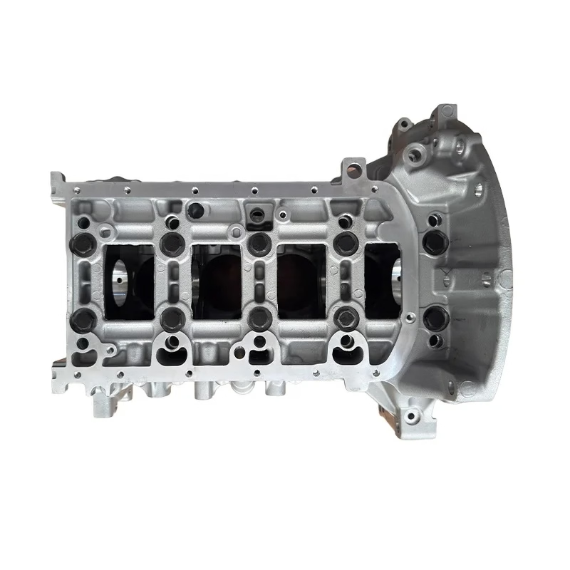
The rotary table adds a fourth axis that is accurate by construction. A Ø400 mm table with a direct-drive or worm gear indexes to within arc-seconds, and the part stays clamped. Bores on opposite faces keep their center distance because they were cut without unclamping. This is the reason horizontal platforms dominate gearbox housings, pump bodies, and engine blocks.
There is a boundary. If the part is a thin plate with features on one face, the rotary table does nothing for you and the horizontal footprint costs more floor space. Long shafts are also awkward: workholding a 1,000 mm shaft on a rotary table is harder than clamping it between centers on a lathe or a mill-turn center.
Matching materials and part shapes to the platform
Horizontal platforms handle the same material range as any CNC mill. Aluminum grades such as 6061-T6, 7075, and ADC12 cut fast and clear chips easily. Stainless 303, 304, 316L, and 17-4PH (SUS630) need lower surface speeds and more coolant, but the falling chip path helps because stainless work-hardens when a chip is recut. Steel grades like 4140, 4340, and 4130 behave well at moderate depths of cut.
Titanium and nickel alloys are where the geometry pays off most. TC4 (Ti-6Al-4V) and Inconel hold heat at the edge. Any recut chip raises the local temperature and shortens edge life. A horizontal spindle with high-pressure coolant through the tool keeps the cutting zone clear. We run these on simultaneous 5-axis platforms where the tool axis can tilt to reach a wall without a long overhang.
Part shape decides more than material does. A good candidate has features on three or four faces, a bore-to-bore tolerance tighter than ±0.02 mm, and a wall or rib that would need a long tool on a vertical machine. A poor candidate is flat, single-faced, or so large that the rotary table cannot swing it. The table capacity sets the real limit, not the spindle.
Volume matters too. One prototype block can be cut on a vertical machine in a couple of setups. Once you need 500 units a month, the pallet changer and the reduced setup count start to pay back. That crossover point sits somewhere around a few hundred parts for a four-face part, and it moves with part complexity.
- 1Good fitPrismatic housings, multi-face bores, ribbed castings.
- 2Poor fitThin single-face plates, very long shafts, one-off simple parts.
- 3Table limitPart must swing inside the rotary table envelope.
Workholding, setup, and where accuracy comes from
Accuracy on a horizontal machine starts at the fixture, not the control. A tombstone fixture holds four or more parts on four faces of a block. Each face has its own work offset, so the operator loads one pallet while the machine cuts another. Setup time drops because the offsets are proven once and reused. The trade-off is fixture cost: a tombstone for a family of parts is a real investment.
The rotary table has to be dialed in before anything else. We indicate the table face and the center bore, then set the part zero from a known datum. If the fixture is not square to the table, every indexed face inherits the error. A 0.01 mm tilt at the fixture becomes 0.01 mm of position error on the far face after a 180° index.
Thermal drift is the slow error. The spindle grows as it warms, and the ballscrews grow with it. On a long run we warm the machine with a dummy cycle, then check a master bore. If the bore is drifting, we adjust the offset rather than chasing it in the program. This is standard practice, not a workaround.
Chip management is a maintenance task. Fine chips from aluminum and cast iron settle in the coolant tank and the chip conveyor. If they are not removed, they get pumped back to the cutting zone and scratch finished surfaces. A horizontal machine with a good conveyor and a clean tank holds finish at Ra 0.8–1.6 μm far more consistently than one with a neglected sump.
What horizontal CNC machining centers can hold in production
A well-maintained horizontal platform holds ±0.005 mm (±0.0002 in) on a bored hole and ±0.01 mm on a position between two holes cut in the same setup. That is the practical number for production, not a lab number. It assumes the fixture is rigid, the tool is short, and the machine has been warmed through.
Surface finish depends on the operation. A face mill with a wiper insert can leave Ra 0.8–1.6 μm on aluminum and steel. Boring or reaming reaches Ra 0.2–0.8 μm when the tool is rigid and the feed is matched to the insert radius. A roughing pass at Ra 1.6–3.2 μm is normal and is usually followed by a finishing pass on any sealing face.
Roundness and cylindricity are where the rotary table earns its keep. Bores cut on opposite faces without unclamping stay coaxial because the part never moves relative to itself. On a vertical machine with two setups, the same pair of bores picks up the error of the second fixture location. That is often the difference between a passing and a failing gearbox housing.
We verify with 100% inspection before shipment, covering raw material check, in-process monitoring, and final inspection. Reports are available on request. If a drawing calls for a capability study, we run the parts and report the actual spread rather than a single pass/fail number.
Horizontal or vertical: which platform fits the part
Pick the layout that matches the part geometry and volume.
| Factor | Horizontal CNC machining centers | Vertical machining centers |
|---|---|---|
| Spindle axis | Parallel to floor | Perpendicular to floor |
| Faces per setup | Three to four on a prismatic block | One, sometimes two |
| Chip clearance | Falls away from the cut | Can pool in pockets |
| Best part shape | Boxy housings with multi-face bores | Flat plates and single-face work |
| Tool overhang | Short tool into a side wall | Long tool into a deep pocket |
| Volume crossover | A few hundred parts per run | Prototypes and low volume |
| Floor space | Larger footprint, pallet pool | Compact for the work envelope |
| Fixture cost | Higher: tombstone or pallet | Lower: vise or plate |
The call we would make
If the part has three or four machined faces, a bore-to-bore tolerance tighter than ±0.02 mm, and a run of a few hundred pieces or more, a horizontal CNC machining center will hold the tolerance with fewer setups. If it is a flat single-face plate, a one-off prototype, or a long shaft, stay on a vertical or mill-turn platform and spend the money on the fixture instead.
Common questions
Is a horizontal machining center more accurate than a vertical one?
Not inherently. The casting and the control matter more than the spindle direction.
The horizontal layout helps accuracy indirectly: fewer setups, shorter tools, and a shorter thermal path. That is why it holds ±0.005 mm more easily on multi-face parts.
What is the largest part a horizontal machine can cut?
It depends on the rotary table and the travel, not the spindle.
On our platforms the largest travel is 4,000 × 400 × 150 mm, and the rotary table is Ø400 mm. The part must swing inside that envelope without hitting the column.
Can a horizontal machine cut deep pockets?
Yes, but the depth-to-diameter ratio still governs the tool.
A horizontal spindle reaches a side wall with a shorter tool, which reduces deflection. For a pocket deeper than about 4× the tool diameter, use a reduced shank or a larger tool and accept a smaller corner radius.
How do you hold a part on a rotary table?
With a tombstone fixture, a dedicated plate, or a vise mounted to the table face.
We indicate the table face and center bore first, then set part zero from a datum on the fixture. Offsets are proven on the first part and reused for the rest of the run.
Does the horizontal layout work for aluminum parts?
Yes, and it is a strong fit for aluminum housings.
Grades such as 6061-T6, 7075, and ADC12 cut fast, and the falling chip path keeps the flutes clear. Surface finish can reach Ra 0.8–1.6 μm with a wiper insert.
When should a part move to a mill-turn center instead?
When the part is mostly round and long.
A shaft with a few cross-holes is faster on a mill-turn center. A horizontal machining center is built for prismatic parts, not for parts that need to spin between centers.
Send us the drawing, get a machining plan
We review your part, tell you which platform fits, and quote within 12 hours. Uploads stay confidential, and an NDA is available on request.
12-hour quote100% inspectionNo minimum orderISO 9001 / IATF 16949
More machining notes
We publish setup notes, tooling trials and inspection data from the factory floor.











