
Casting Process: 5 Proven Steps From Melt to Part
This page explains how the casting process turns liquid metal into a usable blank or part, and where each step goes wrong. It is written for design engineers and buyers who need to pick an alloy, set a draft angle, and decide whether casting or CNC machining fits the job. Read it and you can judge a casting quote line by line.
In this article
- 1
- 2
- 3
- 4
- 5
- 6
- 7
- 8
Key takeaways
What the casting process actually does
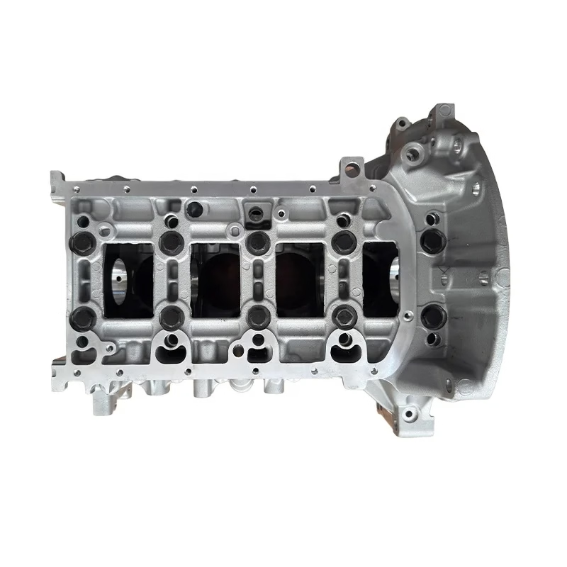
Casting is a liquid metal forming method. You pour molten alloy into a cavity that matches the outside shape of the part, let it freeze, and pull out a blank. The blank is usually not the finished part. It is the near-net shape that a machinist then trims to size, drills, and threads.
The whole route runs in one direction: liquid metal, mold filling, solidification with shrinkage, then the casting itself. Each arrow is a place where the part can fail. Gas trapped during filling becomes porosity. Feeding that stops too early becomes shrinkage voids. A die that is too cold freezes the metal before it reaches the thin sections.
That is why castings are specified with allowances, not just dimensions. You give the foundry a part drawing plus a machining allowance, a draft angle, and a shrinkage factor. The foundry builds the tool from that, and the CNC shop later removes the allowance. Both sides need the same numbers on the print, or the blank arrives 0.8 mm too small on one face.
For low volume work we often skip hard tooling. Die casting needs a steel die and pays off over thousands of parts. Vacuum casting uses a silicone mold and suits 20 to 200 parts. Sand casting handles large, heavy shapes. The casting process itself is the same in all three cases.
- 1Near-net, not netCasting holds roughly ±0.1 to ±0.5 mm on as-cast features, depending on alloy and size.
- 2Wall thickness mattersKeep sections between 2 mm and 6 mm where possible. Thick-to-thin transitions cause hot tears.
- 3One drawing, two shopsMark datum faces and machining stock so the CNC setup matches the casting.
Choosing the alloy before the casting process starts
Alloy choice fixes shrinkage, fluidity, and the corrosion you will live with for years. Aluminum ADC12 flows well and is the default for die casting enclosures and housings. It machines cleanly and takes bead blasting or anodizing. Aluminium 6061 and 7075 are common when the part is cast as a near-net blank and then machined heavily.
Zinc alloys freeze fast, hold fine detail, and cast thin walls down to about 0.8 mm. They are heavier than aluminum and less corrosion resistant without plating. Magnesium AZ91D is the lightest common option for housings, but it needs careful handling because chips and dust burn.
Steel and stainless castings are used where strength or wear resistance matters. Stainless 316 and 17-4PH appear in pump bodies and valve parts. Copper alloys such as C36000 and beryllium copper show up in electrical contacts and busbars because of conductivity. Titanium TC4 (Ti-6Al-4V) is cast for aerospace brackets, but the tooling cost is high and the process window is narrow.
Pick the alloy from the function first, then check whether it casts. A part that must be Ra 0.8–1.6 μm on a sealing face will be machined there anyway. The casting only needs to deliver sound metal and the right bulk shape.
- 1FluidityAluminum and zinc fill thin walls best. Steel needs thicker sections and hotter molds.
- 2Shrinkage rateAluminum about 1.0–1.3%, zinc about 0.4–0.7%, steel up to 2.5%.
- 3MachinabilityADC12, 6061, and C36000 cut fast. Titanium and Inconel cut slow and wear tools.
Design rules that keep the casting process stable
Draft is the first rule. A vertical wall with zero draft will drag, score the die, and tear the part on ejection. Give outside walls 1–2°, inside walls 2–3°, and more on deep pockets. Text and logos on a vertical face need 5° or they will not release cleanly.
Radius every inside corner. Sharp internal corners concentrate stress and block metal flow. A fillet of at least half the wall thickness spreads the load and lets the alloy reach the corner before it freezes. Outside corners can be smaller, roughly one quarter of the wall thickness.
Keep wall sections uniform. A 3 mm wall feeding a 10 mm boss creates a hot spot that shrinks last and pulls a void. Core out thick bosses or step the thickness down over 3 to 5 mm of length. Ribs should be 50–70% of the nominal wall and no taller than five times their thickness.
Plan the parting line early. It decides where flash appears and which faces can be flat. If a cosmetic surface crosses the parting line, expect a visible witness line. Move that surface to a machined face or accept the line in the drawing.
- 1DraftOutside 1–2°, inside 2–3°, text faces 5°.
- 2FilletsInside radius ≥ half wall thickness. Outside radius about one quarter.
- 3Ribs50–70% of wall thickness, height ≤ 5× thickness.
- 4BossesCore them out or blend them into the wall with a taper.
When the casting process beats CNC machining
Casting wins when the shape is complex and the volume is high. An engine housing with internal ribs, bosses, and cooling passages is expensive to cut from solid and cheap to cast once the die exists. Above roughly 5,000 parts a year, die casting usually pays back the tool cost and then drops the piece price.
CNC machining wins when the tolerance is tight, the volume is low, or the material is hard to cast. A bracket needed in three days, held to ±0.005 mm, is a machining job. Casting it would need tooling, a trial shot, and a second setup for the critical faces. The casting process adds days before the first chip is cut.
A mixed route often makes sense. Cast the bulk shape, then machine the sealing faces, bores, and threads. This keeps the tool simple and puts precision only where it is needed. We run this pattern often: the foundry delivers a blank with 0.5–3 mm stock, and our 3-axis and 5-axis machines finish it to ±0.005 mm and Ra 0.8–1.6 μm.
One caution. Cast skin is not as strong as wrought metal and can hide subsurface porosity. If a face carries a fatigue load, machine through the skin or specify a higher grade of casting with radiographic inspection.
- 1Choose castingComplex geometry, volumes above a few thousand, thick sections, internal passages.
- 2Choose machiningTight tolerance, low volume, fast turnaround, wrought material properties.
- 3Choose bothCast the blank, machine only the critical faces and bores.
Checking a casting before it becomes a part
Incoming inspection should look at more than dimensions. Check for cold shuts, visible porosity, flash, and incomplete fill on thin ribs. Tap the part lightly and listen; a dull thud often means an internal void. X-ray or dye penetrant finds what the eye cannot.
Measure the as-cast features at the datum faces first. If the first face is off by 0.5 mm, every downstream cut shifts with it. On parts we machine from castings, we check the raw material, monitor in process, and inspect 100% before shipment. Reports are available on request.
Keep one sample from each lot. When a later part fails a fit check, the retained sample tells you whether the casting moved or the machining drifted. That one habit saves days of argument.
Casting suppliers working to ISO 9001:2015 will have a traceable heat number and a dimensional report. Automotive and medical programs add IATF 16949:2016 and ISO 13485:2016 requirements on top, which tighten process control and documentation.
- 1VisualCold shuts, flash, short fill, surface porosity on machined faces.
- 2DimensionalDatum faces first, then as-cast features, then wall thickness.
- 3SubsurfaceX-ray, dye penetrant, or ultrasonic where the part sees load or pressure.
Step by step: running a casting job from drawing to part
- 11. Fix the alloy and the processMatch alloy to function, then pick die casting, vacuum casting, or sand casting. Confirm shrinkage factor for that alloy, typically 0.4–2.5%.
- 22. Set draft, fillets, and wall thicknessAdd 1–3° draft, inside fillets at half the wall thickness, and hold walls between 2 mm and 6 mm. Remove sharp internal corners.
- 33. Mark machining stock and datumsLeave 0.5–3 mm on faces to be finished. Call out datum A, B, and C so the CNC setup and the casting tool use the same reference.
- 44. Build and trial the toolCut the die or mold, then run a trial shot. Check fill on the thinnest sections first. Adjust gate size or mold temperature before touching the cavity.
- 55. Inspect the first articleMeasure datum faces and as-cast dimensions against the drawing. X-ray or penetrant test if the part carries load or pressure. Sign off before the run.
- 66. Machine the critical facesRough the casting, then finish bores and sealing faces to ±0.005 mm and Ra 0.8–1.6 μm. Relieve stress between roughing and finishing on tight parts.
- 77. Finish and inspect 100%Anodize, plate, or powder coat as specified, then inspect every part before shipment. Keep one sample per lot in case of later questions.
Casting process methods compared
Pick the method from volume, size, and tolerance, not from habit.
| Method | Typical volume | Tolerance as cast | Best for |
|---|---|---|---|
| Die casting | 5,000+ parts | ±0.1–0.3 mm | Enclosures, housings, thin walls |
| Vacuum casting | 20–200 parts | ±0.2–0.5 mm | Bridges, low-volume enclosures |
| Sand casting | 1–500 parts | ±0.5–1.5 mm | Large, heavy, simple shapes |
| Investment casting | 100–10,000 parts | ±0.1–0.4 mm | Fine detail, turbine and medical parts |
| CNC from solid | 1–10,000+ parts | ±0.005 mm | Tight tolerance, fast turnaround |
| Cast then machine | 500–100,000 parts | ±0.005 mm on cut faces | Complex bulk shape plus tight faces |
Cast the shape, machine the tolerance
Use the casting process for complex bulk geometry at volume, and reserve CNC machining for the faces that must hold ±0.005 mm. Split the job that way and you get low piece cost without giving up precision.
Casting process questions engineers ask
How much machining stock should I leave on a casting?
For small parts under 150 mm, leave 0.5–1 mm per face. For medium parts up to 600 mm, 1–2 mm. For large parts, 2–3 mm.
Add more on faces that are warped or that sit opposite a thick section. Too little stock and the cut misses the skin; too much and you waste cycle time.
What causes porosity in a casting?
Gas trapped during filling is the usual cause. It comes from turbulent flow, damp tooling, or vents that are too small or blocked.
Shrinkage porosity is different: the last metal to freeze has nothing to feed it. Fix gas with slower fill and better venting; fix shrinkage with larger gates and proper cooling.
Why does my part have a visible line across the face?
That is the parting line. It appears wherever the two halves of the tool meet, and a small amount of flash is normal.
If the face is cosmetic, move it away from the parting line or plan a light machining pass to remove the witness line.
Can a casting hold ±0.005 mm?
Not as cast. Die casting holds roughly ±0.1–0.3 mm and sand casting is looser.
To reach ±0.005 mm, cast the blank with stock and machine the critical faces. That is the normal route for sealing faces, bores, and bearing seats.
How long does it take to get from drawing to first cast part?
Tooling is the long pole. A simple die or mold takes weeks; a complex one takes longer. The trial shot and first-article inspection follow.
Once the tool is proven, parts run quickly. If you need a functional part in days, CNC machining from solid is usually faster than building a tool.
Is a casting as strong as a machined part?
Not the same. Cast metal has a coarser grain structure and may contain small internal voids, so fatigue strength is lower than wrought stock.
For loaded faces, machine through the cast skin or specify a higher grade with radiographic inspection. For housings and covers, the difference rarely matters.
Send your casting drawing for a free DFM review
We review draft, wall thickness, and machining stock before you commit to tooling, and we quote within 12 hours.
12-hour quote100% inspectionNo minimum order quantity
More machining and casting notes
We publish setup notes, tooling trials and inspection data from the factory floor.











