
Understand the Women Behind CNC Processing Advanced Technology
This page explains how the women behind CNC processing advanced technology shape real shop-floor decisions at GreatLight: CAM programming, material selection, metrology, and process documentation. It is written for engineers and buyers who want to know where that expertise changes a part, a tolerance, or a lead time. Read it if you care about how a shop actually holds ±0.005 mm on a 5-axis job.
In this article
- 1
- 2
- 3
- 4
- 5
- 6
What the women behind CNC processing actually do all day
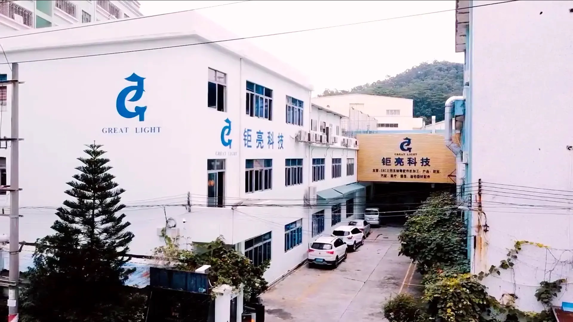
The phrase sounds like a slogan. In a working shop it maps to four concrete jobs: CAM programmer, materials and heat-treat engineer, metrology lead, and process documentation owner. At GreatLight, founded in 2011, these roles sit inside three wholly-owned plants with 150 technicians. The women behind CNC processing advanced technology here are not a separate team; they are the people who decide toolpath order, stock allowance, and inspection strategy on jobs that run from one prototype to 10,000+ parts.
A CAM programmer decides how a part gets cut before any metal moves. That means picking workholding, choosing between 3-axis and simultaneous 5-axis, and setting stock allowance so the part does not spring after the last pass. On a thin-wall aluminum housing, the difference between a 0.5 mm and a 0.3 mm finishing allowance shows up as flatness drift of tens of microns. These calls are made at the computer, not at the machine.
The materials engineer picks the alloy and the condition. A 7075-T6 bracket and a 6061-T6 bracket look identical in CAD. They behave differently after anodizing, and they machine at different feeds. Choosing 17-4PH in the H900 condition instead of annealed changes both the cutting parameters and the final hardness. Wrong call, and you scrap a batch after plating.
The metrology lead defines what 'good' means. A drawing that says ±0.005 mm without a datum scheme leaves the inspection open to argument. The metrology lead sets the datum reference frame, the fixture, and the sampling. That is why 100% inspection before shipment at GreatLight starts with a drawing review, not with a CMM probe.
- 1CAM programmingToolpath order, workholding, 3-axis vs 5-axis, stock allowance
- 2Materials and heat treatAlloy, temper, machinability, post-process behavior
- 3MetrologyDatum scheme, fixture, sampling, report format
- 4Process documentationSetup sheets, tool lists, revision control
Where a CAM decision changes the part
Five-axis simultaneous motion is not automatically better than 3-axis. It is better when the part has features on multiple faces that would otherwise need three or four re-fixtures. Each re-fixture adds a position error. On a manifold with ports on five sides, one 5-axis setup holds a true position of 0.02 mm across all ports. Four separate 3-axis setups typically stack up to 0.05 mm or worse, because each refixture re-datums the part.
Toolpath strategy matters most on thin walls. A 1.5 mm aluminum wall will deflect under a 12 mm end mill at full radial engagement. The fix is not a slower feed alone. It is a smaller stepover (8–12% of tool diameter), a trochoidal path, and a finishing pass from the top down so the wall is supported by the parent material as long as possible. Get this wrong and the wall measures fine on the machine but moves 0.03 mm after unclamping.
Tool life is a programming variable too. In 316L stainless, a coated carbide end mill running at 60–80 m/min surface speed and 0.05 mm/tooth feed will hold size longer than the same tool pushed to 120 m/min. The faster number looks productive on a stopwatch and costs more in tool changes and rework. A programmer who tracks tool wear per part will pick the slower number on a tight-tolerance job.
The 16 simultaneous 5-axis machining centers at GreatLight are paired with 16 mill-turn centers, 12 four-axis mills, and 27 three-axis machines. That mix matters. Routing a simple turned bushing to a 5-axis center wastes spindle time. Routing a 5-face prismatic part to a 3-axis machine adds setups and error. Matching the part to the machine is a daily programming decision, not a sales one.
- 1Use 5-axis whenFeatures on 3+ faces, tight true position between faces
- 2Stay 3-axis whenSingle-face work, simple geometry, high volume
- 3Thin walls8–12% stepover, top-down finishing, light radial engagement
Material selection is a machining decision, not a catalog pick
Engineers often specify an alloy by strength alone. Machinability, heat-treat distortion, and finish behavior matter just as much. 6061-T6 machines cleanly at 300–500 m/min surface speed and anodizes evenly. 7075-T6 is roughly 30% stronger but galls more easily and shows tool marks after clear anodizing. If the part is a cosmetic bracket, 6061 is usually the better call. If it is a load-bearing fitting, 7075 earns its cost.
Stainless grades split sharply. 303 is free-machining and holds Ra 0.8–1.6 μm with little effort. 316L is more corrosion-resistant but work-hardens, so a light feed and a rigid setup are mandatory. 17-4PH in the H900 condition reaches high hardness but is usually machined in the annealed state and then aged. The aging step shrinks the part slightly, and that shrinkage has to be planned into the stock allowance.
Titanium TC4 (Ti-6Al-4V) and Inconel sit at the hard end. Both generate heat at the cutting edge rather than carrying it into the chip. High-pressure coolant, sharp geometry, and conservative speeds (40–60 m/min for Ti-6Al-4V) keep tool life predictable. These are not parts to quote from a generic cost table. They need a process plan before the first cut.
Plastics have their own rules. PEEK and POM move with temperature, so a ±0.005 mm tolerance on a 100 mm PEEK part is realistic only if the shop controls the temperature during cutting and measurement. Carbon fibre reinforced plastic wears tools fast and needs diamond-coated or PCD tooling. Treating a CFRP part like an aluminum part leads to delamination and short tool life.
- 1Aluminum6061, 6061-T6, 2024, 5052, 6063, 6082, 7075, ADC12
- 2Stainless303, 304, 316L, 420, 440C, 17-4PH (SUS630)
- 3Titanium and specialTA1, TA2, TC4 (Ti-6Al-4V), Inconel, AZ31B, AZ91D
- 4PlasticsABS, PC, PMMA, POM, PA, PEEK, PP, HDPE, carbon fibre
Metrology decides whether the tolerance is real
A tolerance is only as good as the measurement behind it. ±0.005 mm (±0.0002 in) is achievable on a rigid part with a clean datum scheme. It is not achievable on a flexible part measured in a different fixture than the one it was machined in. The metrology lead's first question is always: what is the datum, and is it accessible after finishing?
Temperature is the second question. Aluminum expands about 23 μm per meter per °C. A 300 mm aluminum part measured at 25 °C after machining at 22 °C has already drifted roughly 20 μm. For tight work, parts and gauges sit in the inspection room until they stabilize. Skipping that step produces a measurement that looks precise and is wrong.
Sampling strategy follows the drawing. A critical bore with a ±0.005 mm tolerance gets measured on every part. A cosmetic edge break gets checked visually. The quality plan at GreatLight covers raw material check, in-process monitoring, and final inspection, with 100% inspection before shipment and reports on request. That structure exists so the same part measures the same way next month.
The inspection report format matters to buyers. A first article report with actual measured values, not just pass/fail, tells the engineer whether the process is centered or running at the edge of the tolerance band. A process centered at 0.001 mm of nominal is stable. A process running at 0.004 mm of a 0.005 mm band will fail on the next batch.
- 1Datum firstAccessible after finishing, same as machining fixture
- 2Thermal soakLet parts and gauges stabilize before measuring
- 3Report valuesActual numbers, not pass/fail, for critical features
Documentation is what makes the second batch match the first
A good first article proves the process works once. A setup sheet and tool list make it work again. The documentation owner records workholding, tool numbers, speeds, feeds, and inspection points. Without that record, the next run is a new experiment. With it, a repeat order can start production within 24 hours and ship in 3–5 days.
Revision control is part of the same job. When a customer sends a revised drawing, the setup sheet, the CAM file, and the inspection plan all need to move together. If the CAM file is updated but the inspection plan is not, the shop measures the old feature. That kind of mismatch is silent and expensive.
Certifications support this discipline. GreatLight holds ISO 9001:2015, IATF 16949:2016, ISO 13485:2016, and ISO 27001:2022. The first three cover quality systems for general, automotive, and medical work. The fourth covers information security, which matters when customer CAD files and drawings are stored and shared.
Uploads are secure and confidential, and an NDA is available on request. For engineers sending unreleased designs, that is usually a precondition before any file leaves their network. It is a process question, not a marketing one.
- 1Setup sheetWorkholding, tool numbers, speeds, feeds
- 2Inspection planDatum, fixture, sampling, report format
- 3Revision controlCAM, setup sheet, and inspection plan move together
Which process route fits which part
Use this to decide the route before quoting, not after the first article fails.
| Part type | Best route | Why |
|---|---|---|
| Thin-wall aluminum housing | 5-axis, light stepover | Holds flatness without refixture |
| Multi-face manifold | 5-axis simultaneous | True position across all ports in one setup |
| Simple turned bushing | Mill-turn center | One machine, no second op |
| Single-face plate, high volume | 3-axis machine | Fast cycle, low setup cost |
| Cosmetic bracket | 6061-T6, anodized | Even finish, no galling |
| Load-bearing fitting | 7075-T6 or 17-4PH | Higher strength, tighter process control |
| Titanium implant component | TC4, high-pressure coolant | Heat control at the cutting edge |
| PEEK fluidic part | POM/PEEK, temp-controlled | Dimensional stability during and after cutting |
When the advanced route is worth it, and when it is not
If a part has features on three or more faces, tight true position between them, or a wall under 2 mm, route it through 5-axis with a documented metrology plan. If it is a single-face plate or a simple turned part, a 3-axis or mill-turn route will be cheaper and just as accurate. Do not buy 5-axis time for a part that does not need it, and do not push a multi-face part through 3-axis setups to save setup cost.
Questions engineers ask next
Can one shop really hold ±0.005 mm on a 5-axis part?
Yes, on a rigid part with a clean datum scheme and a temperature-stable inspection room. The tolerance applies to specific features, not the whole part.
On flexible or thin-wall parts, ±0.005 mm is realistic only for features measured in the same fixture orientation used for machining. Features measured after unclamping can move 0.02–0.05 mm on a 1.5 mm aluminum wall.
Does 5-axis machining cost more than 3-axis?
The hourly rate is higher, but the total cost can be lower. One 5-axis setup replaces three or four 3-axis setups, each with its own fixture, load, and position error.
For a simple single-face part, 3-axis is cheaper. For a multi-face part with tight true position, 5-axis usually wins on total cost and on scrap rate.
How do you decide between 6061-T6 and 7075-T6?
6061-T6 for general structural and cosmetic parts. It machines cleanly, anodizes evenly, and costs less.
7075-T6 when strength matters more than finish. It is roughly 30% stronger but galls more easily and shows tool marks after clear anodizing.
What surface finishes are available?
As-machined parts run Ra 1.6–3.2 μm. A high-finish pass reaches Ra 0.8–1.6 μm, and fine finishing reaches Ra 0.2–0.8 μm.
Post-processing includes anodizing (clear, colour, hardcoat, conductive), electroless nickel, zinc, silver and gold plating, powder coating, black oxide, bead blasting, tumbling, brushing, polishing, and laser marking with a minimum character height of 1.5 mm.
What is the minimum order quantity?
There is no minimum order quantity. Runs range from one prototype to 10,000+ parts.
For a single prototype, the quote includes a DFM analysis so manufacturability issues are caught before cutting starts.
How fast can a job start and ship?
Quotation and free DFM analysis come back within 12 hours. Production can start within 24 hours, and parts ship in 3–5 days.
The historical late-delivery probability is below 2%. This depends on material availability and on whether the drawing is released for manufacturing.
Send a drawing and get a process plan, not just a price
Quotation and free DFM analysis within 12 hours. Uploads are secure and confidential, and an NDA is available on request.
12-hour quote100% inspectionNo MOQNDA on request
More from GreatLight
We publish setup notes, tooling trials and inspection data from the factory floor.











