
Metal 3D Printing in Mold Manufacturing: 6 Proven Checks Before You Commit
This guide is for mold engineers and tooling buyers who are weighing laser powder bed fusion against CNC-cut inserts. It covers where metal 3D printing mold manufacturing actually pays off, what geometry suits it, and the checks to run before you release a design.
In this article
- 1
- 2
- 3
- 4
- 5
- 6
- 7
Key takeaways
What metal 3D printing mold manufacturing actually changes
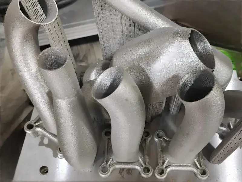
The core change is cooling geometry. A drilled waterline can only run in straight lines, so it sits far from the cavity surface and leaves hot spots between channels. Laser powder bed fusion builds the insert layer by layer, typically 20–60 μm per layer, so the channel can follow the contour of the part at a fixed offset. On a tall core or a deep rib, that offset can be 8–12 mm instead of 25–40 mm.
That shorter thermal path is the whole point. Heat leaves the steel faster, so the part solidifies sooner and you can shorten hold time. On thin-wall packaging parts and long tubular cores, the gain often shows up as a shorter cycle and less warpage. On a flat plate with no hot spots, a drilled line already does the job, and printing buys you very little.
The second change is insert architecture. Instead of printing the entire mold base, most shops print only the core or cavity insert and drop it into a conventionally machined frame. The frame carries the ejector system, guide pillars and clamping, and it stays cheap and easy to rework. The printed insert carries the cooling and the forming surface. This split keeps cost down and makes the printed piece replaceable.
GreatLight runs both sides of that workflow: 127 high-precision CNC machines for the frame, pockets and finishing cuts, plus metal printing for the insert core. One shop means the print-to-machining handoff does not get lost between vendors.
Which parts belong in the printer and which stay on the mill
Print when the cooling path cannot be straight. Typical candidates: deep cores for bottle preforms and thin-wall cups, cores with spiral or bubbler cooling, slides with internal channels, and hot-runner manifolds with curved melt channels. If you can reach the hot spot with a gun drill and a cross-drill, a printed insert is usually not worth the extra cost.
Size is the next filter. Powder bed systems have a build envelope, and a part that needs a long core may have to be split and welded, which adds a joint you then have to inspect. For very large mold plates, the practical answer is a machined plate with printed cooling inserts set into pockets. Small, complex, high-value inserts are the sweet spot.
Material matters too. H13 tool steel and maraging steel are the usual choices for inserts because they harden and hold up in production. For prototype molds or low-run bridge tooling, a printed aluminum or copper-alloy insert can make sense when thermal conductivity matters more than wear life. Copper alloys print with more porosity risk, so plan for a densification check.
Volume is the last filter. One prototype tool with a complex core is often cheaper to print than to fabricate by EDM and drilling, because you skip several operations. A family of twenty similar tools usually favors conventional machining with a standard cooling layout.
Design rules that keep a printed insert from failing
Keep walls between the cooling channel and the forming surface in the 2–4 mm range. Under 1.5 mm the wall is thin enough that residual stress and machining can push the channel closer, and you risk a breakout during polishing. Over 5 mm you lose most of the thermal benefit and the print takes longer.
Give channels a round or teardrop cross-section, 6–10 mm in diameter for typical mold work. Sharp internal corners trap unmelted powder and are hard to clean. Teardrop profiles let unsintered powder drain out of downward-facing channel ends. Every channel needs two open ends or a clear drain path, otherwise powder stays inside.
Support the overhangs. Down-facing surfaces below roughly 45° need support, and those supports must be removable through the pocket or a service hole. Design a flat pad where the recoater can start, and avoid large unsupported horizontal ledges.
Leave stock for finishing. Add 0.3–0.5 mm on faces that will be CNC machined after printing. As-printed surfaces sit around Ra 8–15 μm and carry a stair-step texture from the layer stack. A band, a shutoff or a sealing face needs a cut, not a polish.
Plan the heat treat before the finish cut. Stress relief and hardening move the part. If you machine the shutoff to final size before hardening, you will chase distortion afterward. Rough machine, heat treat, then finish to ±0.005 mm.
Where the process hurts, and how to plan around it
Printed tool steel is porous compared with wrought bar. Gas atomized powder can leave small internal voids, and those voids can open up during polishing or show as pits after texturing. Specify a densification check, and avoid printing a surface that will later be mirror polished or chemically etched to a fine grain.
Distortion is the second issue. Long, thin cores warp during printing and again during hardening. The fix is geometry, not hope: thicker sections, symmetric mass, and generous stock on critical faces. Check the part after heat treat, before the finish cut, and adjust the setup if the part has moved.
Post-processing takes time. You need support removal, powder evacuation, stress relief, hardening, wire EDM or CNC for the fit features, and polishing. That chain is longer than cutting a plain insert from bar stock. If the schedule is tight, budget the post-processing days, not just the print hours.
Cost follows the same logic. A printed insert usually costs more per kilogram than a machined one, and the extra is only recovered through cycle time or part quality. Run the numbers before you commit: if the cycle gain is small, the payback never arrives.
Step by step: from mold design to printed insert
- 11. Map the hot spotsRun a mold flow study or review the cooling layout. Mark every area where the nearest waterline is more than 15 mm from the cavity surface and where the part stays hot longest.
- 22. Split insert from frameDecide which features go into the printed insert and which stay on the machined frame. Keep guide pillars, ejector plates and clamping in the frame. Print only the forming core or cavity.
- 33. Set channel geometryUse 6–10 mm round or teardrop channels, 8–12 mm from the surface, 2–4 mm wall thickness. Give every channel two drain paths and avoid dead ends.
- 44. Add machining stockLeave 0.3–0.5 mm on shutoffs, sealing faces and any surface that will be CNC finished. Model the as-printed surface texture so the CAM programmer knows what to remove.
- 55. Print and evacuate powderPrint in the chosen tool steel, then remove supports and drain unsintered powder from every channel. Verify flow with air or water before moving on.
- 66. Heat treat and stress relieveStress relieve before hardening, then harden to the target range for the steel. Expect small dimensional movement and measure it.
- 77. Machine the critical featuresCNC the shutoffs, locating holes, threads and sealing faces to ±0.005 mm. Finish mold surfaces to Ra 0.8–1.6 μm, or finer where the resin demands it.
- 88. Fit and validateAssemble the insert into the frame, check alignment, then run a short validation shot. Measure cycle time and part dimensions before releasing to production.
Printed insert vs CNC-cut insert: when each wins
Use this to pick the process before you commit tooling budget.
| Factor | Metal 3D printed insert | CNC-cut insert |
|---|---|---|
| Cooling path | Curved, follows cavity contour | Straight drilled lines only |
| Wall to surface | 2–4 mm typical | Limited by drill entry and clearance |
| Geometry freedom | Internal channels, teardrop profiles | No internal curves without splitting |
| Surface as delivered | Ra 8–15 μm, needs finishing | Ra 0.8–1.6 μm off the machine |
| Best part size | Small to medium complex inserts | Any size, including large plates |
| Post-processing | Support removal, heat treat, finishing | Minimal, often one setup |
| Cost driver | Print time and powder | Machine hours and tool wear |
| Cycle time gain | Large on deep cores and hot spots | Small on flat, uniform parts |
Print the cooling, machine the fit
Metal 3D printing mold manufacturing pays off when the hot spot cannot be reached by a drill. Keep the frame conventional, print the insert, and finish every shutoff and sealing face on a CNC to ±0.005 mm.
Common questions
Can a printed insert hold the same tolerance as a machined one?
The printed surface does not. As-printed faces run around Ra 8–15 μm and move during heat treat.
Machine the shutoffs, locating holes and sealing faces after hardening, and those features hold ±0.005 mm like any CNC-cut insert.
How many cycles will a printed tool steel insert last?
It depends on the steel, the hardening and the resin. A hardened H13 or maraging insert behaves much like a wrought one in normal production.
Porosity is the risk. Check density and avoid fine mirror polishing on as-printed surfaces.
Is printing worth it for a single prototype mold?
Often yes when the core is deep or has a hot spot you cannot drill. You skip EDM and cross-drilling steps.
For a simple flat cavity, cutting from bar stock is faster and cheaper.
What channel diameter should we use?
6–10 mm suits most mold work. Smaller channels raise pressure drop and clog risk; larger ones reduce the wall thickness you can keep.
Keep 2–4 mm of steel between channel and forming surface.
How do you remove trapped powder?
Design two open ends or a drain path for every channel, orient channels so powder can fall out, and clear them with air or water before assembly.
Teardrop profiles drain better than sharp rectangular corners.
Do we need a different drawing for the printed insert?
Yes. Send the as-printed model plus a machining drawing that shows stock allowance and the final critical dimensions.
That split lets us print near net shape and machine only what matters.
What lead time should we plan for?
Quotation and DFM feedback come back within 12 hours, and production can start within 24 hours.
Printed inserts carry extra post-processing steps, so confirm the schedule with the shop before you commit a mold trial date.
Send your insert design for a print-and-machine review
Upload the 3D model and we will return a quotation plus free DFM analysis within 12 hours, covering the print orientation, stock allowance and the CNC operations that follow.
12-hour quoteNo minimum order quantity100% inspection before shipment
More mold and machining notes
We publish setup notes, tooling trials and inspection data from the factory floor.











