
What CNC Machine Do: The Engineering Basics
A CNC machine reads a program and moves a cutting tool through metal or plastic, removing material until the part matches the CAD model. This page explains the mechanism, the axes, the real limits on tolerance and finish, and when CNC is the wrong choice.
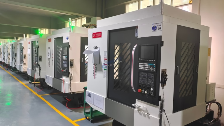
How a CNC machine actually removes material
A CNC machine is a subtractive tool. A CAM post-processor turns your CAD geometry into G-code, and the controller drives servo motors that position a spindle or a turning tool along programmed axes. The tool edge engages the stock and shears chips away. Nothing is molded or added.
Cutting happens at a defined surface speed. In aluminum 6061, carbide end mills typically run 300–500 m/min with feeds of 0.05–0.15 mm per tooth. In 316L stainless, surface speed drops to roughly 120–180 m/min because the alloy work-hardens at the cut. Feed and speed are chosen together, not one at a time.
The machine does not know what the part should look like. It only follows coordinates. That is why setup matters as much as the program. A wrong work offset of 0.5 mm produces a wrong part at full speed. Probing routines and first-article inspection catch this before a run continues.
Heat is the main enemy of accuracy. As the spindle and ballscrews warm up, they expand. A machine that cuts a ±0.005 mm feature cold may drift after two hours. Shops that hold tight tolerances run a warm-up cycle and keep the spindle temperature stable across the shift.
- 1ProgramCAM output defines toolpath, feed and speed.
- 2SetupWork offset and tool length set the origin.
- 3CutServo motion shears chips from the stock.
- 4InspectCMM or gauge confirms the result before the next run.
What 3, 4 and 5-axis machines do differently
A 3-axis mill moves X, Y and Z. The tool always points straight down, so it can reach only the top face of the part in one setup. Holes, slots, pockets and 2D profiles on flat parts are its natural work. It is the cheapest and fastest option when the geometry allows it.
A 4-axis machine adds rotation around one linear axis, usually A around X. This lets the spindle reach several faces without a second setup. For a shaft with cross-holes, or a bracket with features on four sides, 4-axis work removes the repositioning error that hand setups introduce.
A 5-axis machine adds two rotary axes, so the tool can tilt relative to the part. The benefit is not just reach. Tilting the tool keeps a short, stiff portion of the cutter in the cut, which improves surface finish on deep walls and lets short tools reach areas a long 3-axis tool would chatter through.
Simultaneous 5-axis is a different case from 3+2 positioning. In 3+2, the table indexes to an angle and then cuts as a 3-axis move. In simultaneous 5-axis, all five axes move together through a contoured path. That is what makes impellers and complex aerospace surfaces possible, and it is also the hardest to program and verify.
Where turning and mill-turn machines fit
A lathe spins the workpiece and moves a single-point tool along X and Z. Round parts are turned, not milled. A shaft, a bushing or a fitting is faster and more accurate on a lathe than on a mill, because the part rotates on its own axis and the tool never has to reposition around it.
Mill-turn centers combine a spindle that can hold a part with live tooling that can cut on multiple faces. One machine can turn the OD, then mill flats and drill cross-holes without breaking the setup. For parts that would otherwise need two or three operations, this cuts handling time and the error that comes with each move.
The trade-off is setup complexity. A mill-turn center needs more planning and more fixture work up front. It pays off on runs where the part has both turned and milled features and the volume justifies the programming time. On a one-off simple shaft, a plain lathe is the better call.
Tolerance, finish and the real boundaries
Tolerance is not a single number a shop can promise on every feature. It depends on the feature, the material and the setup. GreatLight holds ±0.005 mm on critical features, but a deep bore in 316L is harder than a flat face in 6061. Call out the critical dimensions on the drawing instead of applying a blanket tolerance.
Surface finish follows the same logic. As-machined aluminum lands around Ra 1.6–3.2 μm. Fine finishing with a smaller stepover and a sharper tool reaches Ra 0.8–1.6 μm, and polishing gets to Ra 0.2–0.8 μm on the right geometry. A deep pocket wall will not polish as well as an open face.
CNC has hard limits. A pocket narrower than the smallest available tool cannot be cut. A feature deeper than about four times its width needs a long, thin tool that deflects and chatters. Sharp internal corners can only be as sharp as the tool radius, so a 3 mm end mill leaves a 1.5 mm corner radius.
Material choice changes everything. Aluminum cuts fast and cheap. Titanium and Inconel cut slowly, wear tools quickly and cost more per part. Plastics machine easily but can melt or deform if the feed is too light and the tool rubs instead of cutting.
When CNC is the wrong process
CNC wins on accuracy and material choice. It loses on speed at high volume and on geometry that is cheaper to form than to cut. A stamped bracket at 50,000 pieces costs a fraction of a machined one. A die-cast housing needs no roughing at all.
Thin-walled parts are a weak spot. A wall under 0.5 mm in aluminum flexes under cutting force and springs back after the tool passes. Sometimes the answer is to leave more material, machine in stages, and stress-relieve between passes. Sometimes the answer is sheet metal or 3D printing instead.
Parts with internal channels or lattice structures cannot be machined from solid. Additive processes build them layer by layer. A hybrid approach is common: print the near-net shape, then CNC the critical mating surfaces to tolerance.
The honest test is geometry plus volume. If the part is mostly prismatic, needs tight tolerances, and the run is under a few thousand pieces, CNC is usually the right call. If it is a thin shell or a high-volume simple form, look at forming or molding first.
CNC machine types at a glance
Pick the smallest machine that reaches every feature in one setup.
| Machine type | Best for | Typical tolerance | Watch out for |
|---|---|---|---|
| 3-axis mill | Flat parts, holes, slots, 2D profiles | ±0.01 mm | Undercuts need a second setup |
| 4-axis mill | Shafts, brackets, features on 4 sides | ±0.01 mm | Still limited to one rotary axis |
| 5-axis mill | Contoured surfaces, deep pockets, impellers | ±0.005 mm | Higher programming and setup cost |
| CNC lathe | Round parts, bushings, fittings | ±0.01 mm | No milling without live tooling |
| Mill-turn center | Parts with turned and milled features | ±0.005 mm | Setup planning takes longer |
The short answer
If you need tight tolerance, real material properties and a part that works the first time, choose CNC. If the part is a thin shell or the volume is in the tens of thousands, forming or molding will beat it on cost.
Common questions
What tolerance can a CNC machine hold in practice?
On a stable setup with a rigid tool, ±0.005 mm is reachable on critical features. That is not a blanket number for the whole part.
Deep bores, thin walls and hard alloys push the limit wider. Mark the dimensions that matter and let the shop quote to those.
Which materials can be machined?
Aluminum 6061, 7075 and 2024, stainless 303, 304, 316L and 17-4PH, steels like 4140 and 4340, copper and brass alloys, titanium TC4, Inconel, magnesium, and plastics including POM, PEEK and PC.
Harder and gummier materials cut slower and cost more per part, but they are still machinable.
How long does a CNC project take?
Quotation and DFM feedback come back within 12 hours. Production can start within 24 hours once the drawing and material are confirmed.
Typical parts ship in 3–5 days. Complex 5-axis work or a new fixture adds time to the front end, not the cut.
What finishes are available after machining?
Anodizing in clear, color and hardcoat, electroless nickel, zinc, silver and gold plating, powder coating, black oxide, bead blasting, brushing and polishing.
Laser marking is also available, with a minimum character height of 1.5 mm.
How is design data protected?
Uploads stay confidential, and an NDA is available on request before any file is shared.
We do not reuse customer geometry or show parts without written permission.
Send your drawing, get a real answer
We review the geometry, the material and the critical tolerances, then tell you which machine fits and where the cost sits.
12-hour quote100% inspectionNo MOQ
More from the shop floor
We publish setup notes, tooling trials and inspection data from the factory floor.











