
What Coordinate System Do CNC Machines Use?
Almost every CNC machine works in the Cartesian system: three linear axes X, Y and Z, plus rotary axes on 4-axis and 5-axis machines. This page explains how the machine coordinate system, the work coordinate system and program coordinates relate to each other, and where setup mistakes actually show up on the part.
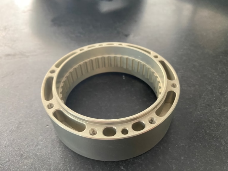
Coordinate system CNC machines use at the machine frame
Every CNC control we run uses the Cartesian coordinate system as its base. Three linear axes sit at 90° to each other: X, Y and Z. Z is normally the spindle axis, X and Y lie in the plane perpendicular to it. A point in space is written as X, Y, Z in millimeters or inches, measured from a fixed origin inside the machine.
That origin is machine zero, sometimes called machine home. The builder sets it, not the operator. On most vertical machining centers, machine zero sits at one corner of the travel envelope, and all three axes move in positive directions from there. On lathes, Z runs along the spindle centerline and X is measured as a diameter, which is why a lathe program shows X twice the actual radial distance.
The third axis matters as much as the first two. Get Z wrong by 0.05 mm and a face mill cuts air or scrapes the table. On a 3-axis machine with 500 × 500 × 450 mm travels, the control only knows where the tool tip is relative to machine zero. It has no idea where your part sits until you tell it.
Machine zero is not a machining datum. It is a reference the control uses to track position. Every other coordinate system in the program is built on top of it, so if the machine loses home position, every offset on that machine becomes suspect until it is re-homed.
Work coordinate systems and G54 to G59
Programming every toolpath from machine zero would be painful. Instead, programmers define a work coordinate system, or WCS, that places the origin on the part. The control stores the distance from machine zero to that part origin as a work offset. G54 through G59 are the standard six offsets on a Fanuc-style control, and most builders add G54.1 P1 through P48 or more.
On a typical job, the operator touches off the top-left corner of the stock, sets that as X0 Y0, and sets Z0 on the top face. The WCS shift goes into the G54 page. The program then reads as if the part corner were 0, 0, 0. Change the part, re-touch the corner, and the same program runs again without a single edit.
This is where most setup errors come from. If the operator sets G54 on the wrong corner, the whole part shifts by the stock dimension. A 100 mm block indexed from the wrong side moves every feature 100 mm. The toolpath is perfect. The part is scrap.
Multiple offsets let one machine run several vices or a tombstone fixture in one cycle. G54 on station one, G55 on station two, G56 on station three. Each station has its own origin, and the program calls the offset before each tool change. The control does the arithmetic.
Absolute, incremental and how the control reads them
Inside a program, coordinates appear in two forms. Absolute moves (G90) tell the tool where to go from the part origin. Incremental moves (G91) tell it how far to travel from where it stands now. Most production programs run G90 for positioning and G91 for short repeat moves such as drilling a row of holes at a fixed pitch.
Mixing the two by accident is a classic crash. If a block written for G91 runs while the control is still in G90, the tool goes to an absolute point far from the cut. We keep a safe-start block at the top of every program: G90 G54 G17 G40 G49 G80, plus a spindle speed and a tool length call. That single line prevents most of the mistakes we see.
Tool length offsets live in a separate register from the work offset. The control adds the tool length to the Z work offset at run time, so one program can call ten different tools and each one knows where its tip is. If a tool is measured into the wrong register, the error shows up as a Z shift that matches the difference between the two tools.
Cutter compensation is the last coordinate layer. G41 and G42 shift the tool center away from the programmed path by the radius in the offset table, so the programmer can dimension the part edge instead of the tool center. Wear offsets then nudge that radius by a few microns to hold a tolerance like ±0.005 mm without reposting the program.
Rotary axes, G68 and 3+2 orientation
A 4-axis machine adds a rotary axis, usually A around X or B around Y. The coordinate system stays Cartesian, but one linear axis is replaced by an angular value. On a horizontal tombstone, B90° means the part has rotated a quarter turn, and the X and Z directions that the tool sees have swapped relative to the part.
Five-axis machines add two rotary axes, and the control has to track the tool tip through both of them. Modern controls do this with TCPC, sometimes called RTCP. The programmer writes the tip position and the control solves the pivot, so the part does not move when the rotary axes tilt. Without TCPC, every tilt angle needs its own posted program.
G68 coordinate rotation handles simpler cases. It rotates the XY plane by an angle around a defined center, which is useful when a feature pattern sits at an odd angle on a plate. Mill a slot at 30° by rotating the coordinate frame instead of reprogramming the path. Cancel it with G69 before the next operation.
Tilted work planes go one step further. G68.2 or a control-specific cycle defines a plane that is not parallel to the table, and the control transforms all three axes so a 3-axis style program cuts on that tilted face. This is common on 3+2 setups, where the rotary axes index to a position and then lock. It gives five-face access with three-axis programming habits.
On our 16 simultaneous 5-axis centers, the rotary table is Ø400 mm. Parts that need five-sided access in one setup usually fit that envelope; larger parts go on the 4,000 × 400 × 150 mm travel machines and run as multiple setups.
Machine, work and program coordinates side by side
Each system answers a different question.
| System | Origin set by | Typical use |
|---|---|---|
| Machine coordinates | Machine builder, at home position | Axis travel limits and reference returns |
| Work offset (G54–G59) | Operator, by touching off the part | Placing the part origin on the stock |
| Program coordinates | CAM programmer | Describing the toolpath |
| Tool length offset | Tool setter or operator | Making each tool tip agree with Z0 |
| Cutter compensation | Operator, in the wear table | Holding size without reposting |
| G68 rotation | Programmer, with a center and angle | Angled features on one plane |
| G68.2 tilted plane | Programmer, with a plane definition | Cutting on a non-parallel face |
Which one do you actually touch?
For 3-axis work, set the work offset at G54 and leave machine zero alone. For 4-axis and 5-axis work, insist on TCPC and a verified rotary center, because a wrong pivot shows up as a taper that no tool offset can fix.
Questions engineers ask about CNC coordinates
Do all CNC machines use the same coordinate system?
Nearly all use the Cartesian system with X, Y and Z, and the axis directions follow ISO 841. What changes is how many axes exist and how the control handles them.
A 3-axis mill has three linear axes. A mill-turn center may have X, Y, Z, C and a sub-spindle. The naming convention stays the same, but the machine zero and the available offsets differ.
Why does my part come out shifted even though the program is correct?
The work offset is almost always the cause. Check which corner was touched off and whether the G54 values match the setup sheet.
A second cause is a stale offset from a previous job. Clear G54 through G59 before a new setup instead of editing over the old numbers.
What is the difference between G54 and G92?
G54 is a stored work offset that survives power cycles and can be recalled at any time. G92 shifts the coordinate system from inside the program and is easy to lose track of.
We prefer G54-style offsets for production. They are visible in the offset page, so the next operator can see exactly what was set.
Can a CNC machine cut a part without a work offset?
Yes, if the program is posted from machine zero. That is common in toolroom work where one operator runs one part.
In production it costs time. Every new blank needs the same stock position, and one misloaded part scraps the cycle. Work offsets remove that risk.
How does 5-axis machining change the coordinate system?
Two rotary axes are added, and the control must compensate for the pivot distance between the rotary center and the tool tip. That function is TCPC or RTCP.
With TCPC active, the programmed point is the tool tip, and tilting the table does not move the cut. Without it, the part shifts as the rotary axes move, and the post processor has to correct every block.
Does the coordinate system affect achievable tolerance?
It sets the floor. If the work offset or rotary center is wrong, no amount of tool offset tuning will hold ±0.005 mm.
Once the offsets are correct, thermal drift and tool wear become the limit. That is why we inspect 100% of parts before shipment and can supply reports on request.
Send us your part and we will set the offsets
Upload a STEP file and our engineers return a quotation with free DFM analysis within 12 hours. Production can start within 24 hours, and parts ship in 3–5 days.
12-hour quote100% inspectionNo minimum order quantityNDA on request
More machining notes from the shop floor
We publish setup notes, tooling trials and inspection data from the factory floor.











