
CNC Machine: How Does It Work?
A CNC machine is a machine tool that follows a program instead of a handwheel. This guide walks the full chain from CAD model to inspected part, and shows where tolerance is actually won or lost.
Key takeaways
What a CNC Machine Really Is
A CNC machine is a machine tool whose axes are driven by motors under numerical control. The operator does not turn a handwheel. Instead, a control reads a program of coordinates and switch commands, and the machine repeats that motion exactly on every part.
The program is written in G-code: positions on X, Y and Z, feed rates in mm/min, spindle speeds in rpm, and M-codes for coolant, tool changes and program stop. A lathe uses two axes (X and Z) plus a spindle that rotates the work. A mill uses three linear axes, and a 5-axis center adds two rotary axes so the tool can reach five faces in one setup.
Subtractive means material comes off. A block of 6061-T6, a 316L bar or a titanium forging goes in, and a finished geometry comes out. Nothing is pressed or cast into shape. That is why CNC holds tight tolerances on low and medium volumes, and why deep pockets and thin walls need extra thought.
The machine itself is only half of the system. Tooling, workholding, coolant and the measuring instruments around it decide whether the drawing is met. A good control on a bad fixture still produces bad parts.
When a CNC Machine How Does It Work Best
CNC suits parts with tight tolerances, complex geometry, or a need for repeatability across a batch. If your drawing calls for ±0.005 mm on a bore, or a contoured surface that must match a mating part, this is the process to use.
It also suits low to medium volume. A single prototype and a 10,000-piece run use the same program, so the first part and the last part come off the same path. Setup cost is paid once, then the cycle time repeats.
It is less suitable when the geometry is simple and the volume is very high. A stamped bracket or a die-cast housing will beat CNC on unit cost once tooling is amortized. CNC still makes the prototype and the tooling insert.
Material choice matters too. Aluminum 6061 and 7075 cut fast and hold finish well. Stainless 316L and 17-4PH work-harden, so feeds and speeds must be right or the tool rubs. Titanium TC4 and Inconel need low surface speed, rigid setups and plenty of coolant.
Which CNC Machine How Does It Work for Your Part
A 3-axis mill moves the tool in X, Y and Z while the part stays still. It is the workhorse for plates, brackets and pockets that can be reached from one direction.
A 4-axis mill adds a rotary table, usually Ø400 mm, so the part can be indexed to a second face without re-clamping. Good for parts with features on four sides.
A 5-axis center adds two rotary axes and moves them at the same time. That lets a short, stiff tool reach undercuts and blend surfaces in one setup. Impellers, medical housings and complex automotive parts are typical.
A mill-turn center combines turning and milling in one machine. Parts that need a turned diameter plus cross-drilled holes avoid a second setup, which removes one source of position error.
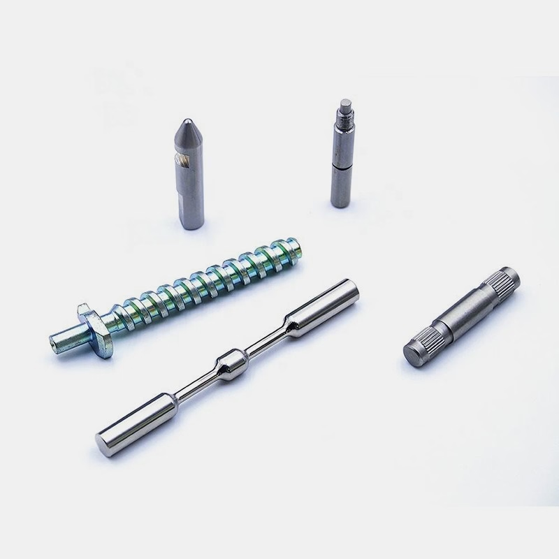
A lathe, or turning center, rotates the workpiece and moves a single-point tool. Shafts, bushings, fittings and threaded parts belong here. Live tooling lets the same machine drill and mill off-axis.
Step by Step: CNC Machine How Does It Work
Seven steps from model to inspected part
- 11. Read the drawing and set the datumsIdentify the functional surfaces first. Pick datum A as the surface that mates with the next part, then B and C. Check every tolerance is reachable: ±0.005 mm is fine on a bored hole, but not on a long unsupported wall. Flag any GD&T callout that needs a specific fixture.
- 22. Build the CAD model and check itModel to nominal, then confirm wall thickness, tool reach and corner radii. A pocket with a 2 mm internal corner needs a 2 mm cutter, which is slow and easy to snap. Open it to 3 mm if the design allows. Check the units are millimeters, not inches.
- 33. Generate the CAM programChoose the stock size, set the work coordinate system on the drawing datums, and select tools. Rough with a 0.3–0.5 mm radial stepover, then finish with a 0.1–0.2 mm stepover. Set feed and speed from the material: 6061 aluminum runs fast, 316L runs at roughly a third of that speed.
- 44. Simulate and post-processRun the toolpath simulation and look for gouges, collisions and rapid moves through the part. Then post to the machine control. Check the G-code header for the right work offset, tool numbers and coolant commands before you send it.
- 55. Set up the workholding and touch offClamp on a sacrificial area or use soft jaws so the part is not distorted. Indicate the fixture within 0.01 mm. Touch off tools on the setting block and record the offsets. Confirm the first tool is the one the program expects.
- 66. Cut the first article and measure itRun with the feed override at 50% for the first passes. Then measure the critical features on a CMM or a micrometer. Compare against the drawing, not against the model. If a bore is 0.02 mm small, correct the tool offset and re-cut before running the batch.
- 77. Run the batch and inspect at the endOnce the first article passes, release the program and check parts at intervals through the run. Do a final inspection of 100% of the parts before shipment. Keep the inspection report with the job.
Choosing the Process for the Part
Match the geometry and volume to the right method
| Situation | Best process | Why |
|---|---|---|
| Tight tolerance, one-off prototype | 3-axis or 5-axis CNC | Program change is free, no tooling cost |
| Complex contoured surface | 5-axis CNC | Short tool reaches blends in one setup |
| Simple part, 50,000 per year | Die casting or stamping | Tooling amortizes over high volume |
| Turned shaft with cross holes | Mill-turn center | One setup, no re-clamp error |
| Thin wall under 1 mm | CNC with light finishing passes | Spring passes control deflection |
| Large plate up to 4,000 mm | Gantry-style 3-axis | Travel covers the full part length |
Frequently Asked Questions
Does a CNC machine need an operator?
Yes, but the role changes. The operator loads stock, sets offsets, checks tool wear and measures parts. The cutting path itself runs from the program.
One operator can run several machines at once if the cycle times are long enough and the tool life is predictable.
How tight a tolerance can CNC hold?
On a rigid setup with the right tooling, ±0.005 mm is achievable on bores and flat surfaces. It is not automatic. Long thin parts, deep pockets and hard materials move that number.
Tell us which features are critical so the setup and inspection plan can be built around them.
What file formats do you need for a quote?
STEP and IGES are the safest for 3D geometry. Native SolidWorks, Fusion 360 and Inventor files also work. For 2D parts, a DXF or PDF with dimensions is enough.
Include the material, finish, quantity and any critical tolerance callouts. That removes most of the back-and-forth.
How long does it take to make a part?
Quotation and a free DFM analysis come back within 12 hours. Production can start within 24 hours after the order is released.
Typical parts ship in 3–5 days depending on quantity and finish. Complex 5-axis work and special finishes take longer.
Can you machine a single prototype?
Yes. There is no minimum order quantity. We run from one prototype up to 10,000+ part runs on the same program.
Uploads are kept secure and confidential. An NDA is available on request if your project needs one.
Which materials can be machined?
Aluminum 6061, 7075 and 6082; stainless 303, 304, 316L and 17-4PH; steels 1018, 4140 and 4340; copper and brass; titanium TC4 and Inconel; plus plastics such as POM, PEEK and PC.
Hard materials cut slower and need more rigid setups. Send the material grade with your files so the quote reflects the real cycle time.
Send Your Files, Get a Plan
Upload a STEP file and we will return a quotation with a free DFM analysis within 12 hours.
12-hour quote100% inspectionNo minimum order
More from GreatLight
We publish setup notes, tooling trials and inspection data from the factory floor.











