
What Turning and Planing Mean in the Machine Shop
Two cutting motions that shop masters name in the same breath, yet they act on metal in opposite ways. This page explains the mechanics of turning and planing, what each process can and cannot hold, and how to decide which one fits a given part.
What Turning Actually Does to Metal
Turning rotates the workpiece and feeds a single-point tool along its surface. The spindle holds the part in a chuck, collet or between centers. The tool stays fixed on the turret while the part spins. Material comes off as a continuous chip, and the diameter drops by twice the depth of cut.
Cutting speed is set by the surface speed of the rotating part, not by a table traverse. A Ø50 mm aluminum bar at 3,000 rpm runs at about 470 m/min at the surface. Drop to Ø10 mm and the same spindle speed gives only 94 m/min. That is why small diameters need higher rpm to keep the chip load sane.
Feed is expressed in mm per revolution. A typical roughing pass on 6061-T6 runs 0.2–0.3 mm/rev at 2–3 mm depth of cut. Finishing passes drop to 0.05–0.1 mm/rev and 0.2–0.5 mm depth to hold Ra 0.8–1.6 μm. The tool nose radius sets the floor on finish.
Turning is a continuous-cut process. The tool stays engaged, so thermal load is steady and tool wear is predictable. That makes it the default for any part that is mostly round: shafts, bushings, pins, adapters, valve bodies.
- 1Good forCylindrical parts with a single axis of symmetry
- 2Speed driverSurface speed, so rpm must rise as diameter falls
- 3Finish controlFeed rate and nose radius, not spindle speed
What Planing Does and Why It Still Exists
Planing moves the tool or the table in a straight reciprocating stroke across a flat surface. The part is clamped to a table, and a single-point tool takes a linear pass. On the return stroke the tool lifts clear, so cutting happens in one direction only.
The motion is intermittent. Each stroke starts from zero velocity, accelerates, cuts, then decelerates. That start-stop cycle limits cutting speed. A shaper or planer might run 10–40 strokes per minute, far below the surface speeds a lathe reaches.
Because of that, planing is slow. It survives where the part is too long, too heavy or too awkward to fit on a mill table, or where the setup must stay rigid against interrupted cuts. Large machine beds, guideways and base plates are the classic cases.
Modern shops often replace planing with face milling or surface grinding. Milling gives higher metal removal rates. Grinding gives tighter flatness. Planing sits between them: cheaper tooling than grinding, better flatness than a light mill pass on a flexible setup.
- 1MotionLinear reciprocating stroke, one direction cuts
- 2LimitStart-stop cycle caps cutting speed
- 3Still used forLong beds, guideways, heavy base plates
Tool Geometry and Material Choices
Turning tools are usually indexable inserts in a holder. Carbide covers most work. Coated grades handle steel and stainless; uncoated polished grades run better on aluminum to avoid built-up edge. High-speed steel still appears for form tools and low-volume work.
Insert shape sets what the tool can reach. A 80° diamond is strong and handles roughing. A 55° or 35° diamond reaches into corners and shoulders but has a weaker tip, so depth of cut must drop. Nose radius trades finish against vibration: bigger radius gives smoother finish but can chatter on slender parts.
Planing tools look similar but are ground with more rake and clearance because the stroke is interrupted. Each entry into the cut is a small impact. Tool holders are heavier to absorb that shock. Carbide is common, but brazed tips and high-speed steel survive better where the setup is not fully rigid.
For either process, the material drives the grade. Aluminum 6061 and 7075 cut freely at high rake. Stainless 304 and 316 work-harden, so the tool must stay engaged and feeds must not dwell. Titanium TC4 needs lower surface speed and copious coolant to keep heat out of the edge.
- 1AluminumHigh rake, polished insert, watch built-up edge
- 2StainlessNever dwell; keep the edge cutting
- 3TitaniumLower speed, high coolant pressure
When Each Process Is the Wrong Choice
Turning struggles with non-round features. A square flange, a slot or an off-axis hole cannot be produced by rotation alone. Those need a mill, or a mill-turn center that adds a rotary tool axis to the lathe. Trying to force them onto a lathe means extra setups and stacked tolerance error.
Long slender shafts are another limit. Radial cutting force pushes the part away from the tool, so the middle of the shaft bows. The result is a barrel-shaped diameter. A steady rest or a follow rest helps, but past a length-to-diameter ratio of about 10:1 the process gets difficult to hold at ±0.005 mm.
Planing loses to milling on almost every flat part that fits on a mill table. If the part is under 1,000 mm and the flatness callout is normal, face milling is faster and cheaper. Planing only wins when the part is too large to move, or when the setup needs the stiffness of a planer bed.
Neither process handles thin walls well. Turning a thin-walled tube distorts it as the chuck closes and again as the cut releases residual stress. Planing a thin plate bows it under clamp pressure. In both cases, light passes and better fixturing help, but the geometry may simply call for a different process.
- 1Non-round featuresNeed milling or mill-turn
- 2L/D over 10:1Deflection limits turning accuracy
- 3Thin wallsClamp and residual stress distort the part
How These Processes Fit Modern CNC Work
Most parts today are not purely turned or purely planed. A mill-turn center does both in one setup. The part is turned on the main spindle, then a live tool mills flats, drills cross holes and cuts slots without re-chucking. That removes the tolerance stack from moving the part between machines.
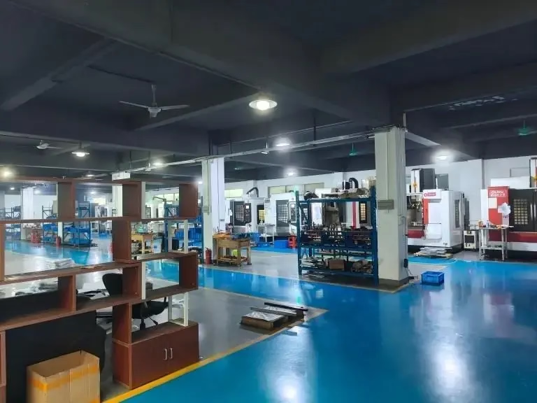
At GreatLight we run 16 mill-turn centers alongside 16 simultaneous 5-axis machining centers, 12 four-axis mills and 27 three-axis machines. The mix matters because a turned part with a few milled flats should not be split across two machines if one setup can hold it.
Setup count drives cost more than cutting speed does. Every re-chuck adds a positioning error and a queue. If a part can be turned and milled in one fixture, the shop saves both. That is usually worth more than a slightly faster spindle.
Inspection closes the loop. We check raw material on arrival, monitor in process and inspect 100% before shipment, with reports on request. For a turned shaft, that means diameter, runout and surface finish get measured, not assumed.
- 1One setup winsFewer chucks means less stacked error
- 2Machine mixMatch the process to the feature, not the habit
- 3Verify, do not assumeMeasure diameter, runout and finish
Turning vs Planing: Quick Comparison
Use this to pick the process before you write the setup sheet.
| Factor | Turning | Planing |
|---|---|---|
| Primary motion | Workpiece rotates | Tool or table strokes |
| Typical geometry | Round, axial symmetry | Flat, long, heavy |
| Cut continuity | Continuous | Intermittent |
| Surface speed | High, 100–500 m/min | Low, 10–40 strokes/min |
| Finish capability | Ra 0.2–1.6 μm | Ra 1.6–3.2 μm |
| Best size range | Ø1–Ø400 mm | Up to 4,000 mm long |
| Common replacement | Mill-turn centers | Face milling, surface grinding |
The Verdict
If the part is round and fits a chuck, turn it. If it is flat, long and heavy, and milling cannot reach the setup, plane it. Everything else belongs on a mill-turn or 5-axis center where one setup does both.
Frequently Asked Questions
Is planing still used in production shops?
Yes, but for a narrow set of parts. Large machine beds, guideways and base plates that are too long or too heavy for a mill table still go on a planer.
For anything under about 1,000 mm with a normal flatness callout, face milling or surface grinding is faster and cheaper.
Can a lathe produce a flat surface?
It can face the end of a round part, which produces a flat disc. That is still turning, because the part rotates.
It cannot produce a long flat surface along the part axis unless you add a live milling tool, which turns the machine into a mill-turn center.
What tolerance can turning hold?
On a rigid setup with the right insert, turning holds ±0.005 mm on diameter. Surface finish lands in the Ra 0.2–0.8 μm range with a fine finishing pass.
The practical limit comes from part stiffness, not the machine. Long slender shafts deflect and lose the tolerance before the machine runs out of accuracy.
Why does planing leave a rougher finish than turning?
Because the stroke starts and stops. The tool enters the cut at zero velocity, so the first few millimeters cut differently than the middle of the stroke.
That intermittent engagement shows up as a pattern on the surface. Turning keeps the tool engaged continuously, so the finish is more uniform.
When should a part move to a mill-turn center?
When it has both round and non-round features. A turned body with milled flats, cross holes or slots is the classic case.
Doing both on one machine removes a re-chuck, which removes a positioning error and a queue. That usually beats any gain from splitting the work across two faster machines.
Send Us the Drawing
We review the geometry, pick the process and come back with a quotation and free DFM analysis within 12 hours.
12-hour quote100% inspectionNo minimum order quantity
More Machining Notes
We publish setup notes, tooling trials and inspection data from the factory floor.











