
Whats CNC Machine? The Basics, the Limits, the Trade-offs
A whats cnc machine question usually means one thing: how does a machine tool cut metal from a program instead of a handwheel? The controller reads coordinates and switch states, then drives servo motors to cut metal, plastic or composite to a defined shape. This page explains the mechanism, the axis options, and when a cnc machine is the wrong call for a part.
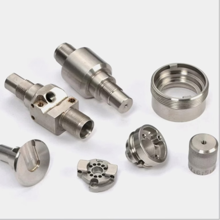
Whats cnc machine, inside the enclosure
A whats cnc machine is a machine tool under numerical control. The operator no longer turns a crank or watches a dial. A program holds the tool path as coordinates and feed rates, and the controller turns those numbers into motion. The cutting action is the same as manual milling or turning. What changed is who decides where the tool goes next.
The loop is closed. A servo motor drives a ballscrew or a linear motor, and a rotary encoder reports the actual position back to the controller thousands of times per second. When the axis lags, the controller corrects it before the cutter reaches the next block of code. That feedback is why a cnc machine can hold ±0.005 mm while a manual mill drifts as the operator gets tired.
The program itself is plain text. G-codes call moves, plane selection and canned cycles; M-codes handle spindle, coolant and tool change. Feed rate, spindle speed and tool number sit in the same file. A typical finishing pass on aluminum 6061 might run at 8,000 rpm and 2,500 mm/min with a 6 mm three-flute end mill.
The controller does not understand the part. It understands motion. If the CAM output is wrong, the cnc machine will cut the wrong shape with perfect repeatability. That is the trade-off: consistency without judgement.
The five hardware groups that make it repeatable
Every cnc machine needs five groups working together: frame and guideways, drive system, spindle, tooling interface, and the control unit. The frame carries the cutting load. Cast iron or polymer concrete absorbs vibration; a welded steel frame on large gantries trades some damping for travel length.
The drive system is where accuracy comes from. Ground ballscrews with preloaded nuts suit most milling work. Linear motors remove backlash and pitch error entirely, but they cost more and consume more power at idle. A rotary table adds a fourth or fifth axis without moving the part between setups.
The spindle sets the material window. A 12,000 rpm spindle with HSK or BT30 tooling cuts aluminum and plastics well. Titanium and Inconel need lower rpm, higher torque, and rigid toolholders. Coolant-through-spindle helps deep holes in stainless and avoids chip recutting.
Tooling and the control unit finish the picture. Tool length offsets and work offsets let one program run on any qualified machine of the same type. That is how a shop keeps a part identical across three plants.
- 1FrameAbsorbs vibration; cast iron for rigidity, gantry steel for long travel
- 2DrivesBallscrew or linear motor; servo feedback closes the position loop
- 3SpindleSets rpm, torque and coolant path for the material
- 4ControlRuns G-code, applies offsets, logs alarms and tool life
From CAD file to finished part
The workflow starts with a 3D model and a defined tolerance callout. The engineer chooses stock size, fixturing and the datum scheme before any toolpath is written. Datum choice decides how much error stacks up in the finished part.
CAM software generates the toolpath, then post-processing converts it to the machine's G-code dialect. The operator proves the program, sets work offsets, and checks the first article. On a 5-axis job, the post-processor must handle tool center point control or the part will not match the model.
Cutting happens in stages: roughing removes bulk stock with high feed and deep axial cuts, semi-finishing equalizes stock, finishing hits the callout surface and tolerance. In-process probing catches drift before the part leaves the machine.
Final inspection closes the loop. A CMM or optical comparator confirms dimensions against the drawing. Reports are available on request, and we inspect 100% of parts before shipment.
- 1Design reviewDFM feedback on radii, wall thickness, tool reach
- 2SetupFixturing and datum scheme chosen before toolpath
- 3CuttingRough, semi-finish, then finish to the tolerance callout
- 4InspectionFirst article plus 100% final check before shipping
3-axis, 4-axis, 5-axis: where each one stops
A 3-axis cnc machine moves on X, Y and Z only. It is the cheapest way to cut flat plates, pockets, holes and shallow 3D surfaces. Most brackets, enclosures and prototype plates never need more. The limit appears when a feature sits on a face that the spindle cannot reach without a second setup.
A 4-axis machine adds rotation around one axis, usually A. The part turns while the tool stays on the same plane. Gears, impellers and cylindrical parts with cross-holes become one-setup jobs. Positional 4-axis indexing is simple; simultaneous 4-axis contouring needs a solid post-processor.
A 5-axis machine adds two rotary axes, either trunnion table or spindle tilt. It reaches undercuts, deep pockets and compound angles in a single setup. Tool center point control keeps the tip on path while the table rotates. That reduces fixture count and setup error, which matters most on complex, low-volume parts.
More axes is not automatically better. A 5-axis cycle is slower to program and slower to cut on simple geometry. The right question is how many setups the part needs, not how many axes the shop owns.
- 13-axisFlat and prismatic parts, one face per setup
- 24-axisCylindrical and indexed features, fewer setups
- 35-axisUndercuts and compound angles in one setup
What the machine can and cannot cut well
Aluminum 6061, 7075 and 2024 cut fast and hold tight tolerances with the right coolant and tooling. Stainless 304 and 316 work-harden, so the tool must keep moving. Titanium Ti-6Al-4V and Inconel need low surface speed, rigid setups and more tool changes.
Plastics behave differently. POM and PEEK machine cleanly with sharp carbide and air blast. ABS and PC soften with heat, so light passes and vacuum fixturing beat heavy clamping. Carbon fibre eats tool edges, so diamond-coated cutters are the practical choice.
Some geometry is simply wrong for a cnc machine. Very deep narrow slots, thin unsupported walls under 0.5 mm, and internal cavities with no tool access cannot be cut from solid. Those parts usually move to die casting, 3D printing or a split design.
Hardened tool steel above 45 HRC needs either soft machining before heat treat or EDM after. A cnc machine with the wrong tooling will cut it, slowly and expensively.
When a cnc machine fits, and when it does not
Match the part to the process before pricing it.
| Part condition | Best fit | Why |
|---|---|---|
| Flat plate, holes, pockets | 3-axis milling | One setup, lowest cost per part |
| Cylindrical with cross-holes | 4-axis or mill-turn | Rotation replaces a second setup |
| Undercuts, compound angles | 5-axis simultaneous | Single setup, fewer fixtures |
| Wall under 0.5 mm, no support | Not CNC from solid | Chatter and deflection break tolerance |
| Internal cavity, no tool access | Die casting or 3D printing | Cutter cannot reach the feature |
| Hardened steel above 45 HRC | Soft machine, then grind or EDM | Carbide tool life collapses |
Pick the process before the machine
If the part is prismatic and needs tight tolerance, a 3-axis cnc machine is the cheapest proven route. If it has undercuts or compound angles and the setup count is climbing past three, move to 5-axis. If the geometry cannot be reached by a rotating cutter at all, CNC is the wrong process and no axis count will fix it.
Common questions about whats cnc machine
What materials can a cnc machine cut?
Aluminum 6061, 6061-T6, 2024, 5052, 5083, 6063, 6082, 7075 and ADC12. Stainless 303, 304, 316, 316L, 17-4PH, 420 and 440C. Steel 1018, 1045, 4130, 4140, 4340 and tool steel.
Titanium TA1, TA2, TC4, plus Inconel and magnesium AZ31B. Plastics include ABS, PC, PMMA, POM, PA, PEEK, PP, HDPE and carbon fibre.
How tight can a cnc machine hold?
We hold ±0.005 mm (±0.0002 in) on qualified features. Surface finish runs from Ra 0.2–0.8 μm on fine finishes to Ra 1.6–3.2 μm as machined.
The achievable number depends on material, feature depth and how the part is fixtured. Deep bores and thin walls move the limit.
How long does a quote and a first run take?
Quotation and free DFM analysis come back within 12 hours. Production can start within 24 hours, and parts ship in 3–5 days.
Historical late-delivery probability is below 2%. There is no minimum order quantity, from one prototype to 10,000+ part runs.
Do you handle finishing after machining?
Yes. Anodizing (clear, colour, hardcoat, conductive), electroless nickel, zinc, silver and gold plating, powder coating and black oxide.
We also run bead blasting, tumbling, brushing, polishing, and laser marking with a minimum character height of 1.5 mm.
How is part data protected?
Uploads are secure and confidential. An NDA is available on request before you send drawings.
Our quality system is certified to ISO 9001:2015, IATF 16949:2016, ISO 13485:2016 and ISO 27001:2022.
What size parts can you machine?
Maximum processing size is 4,000 mm, with large travel at 4,000 × 400 × 150 mm and medium travel at 750 × 1,150 × 550 mm or 600 × 600 × 600 mm.
Compact work runs on 500 × 500 × 450 mm and 500 × 310 × 200 mm machines, with a Ø400 mm rotary table available.
Send the drawing, get a real process answer
Upload your CAD file. An engineer reviews the geometry, suggests the axis count and process, and returns a quote with DFM notes within 12 hours.
12-hour quote100% inspectionNo MOQ
More machining notes
We publish setup notes, tooling trials and inspection data from the factory floor.











