
Which CAM Software Supports Complex Multi Axis Machining?
Five platforms handle most simultaneous 5-axis work, but they differ in how toolpaths are generated, how collisions are checked, and how easily your post-processor gets edited. This page gives you the judging criteria.
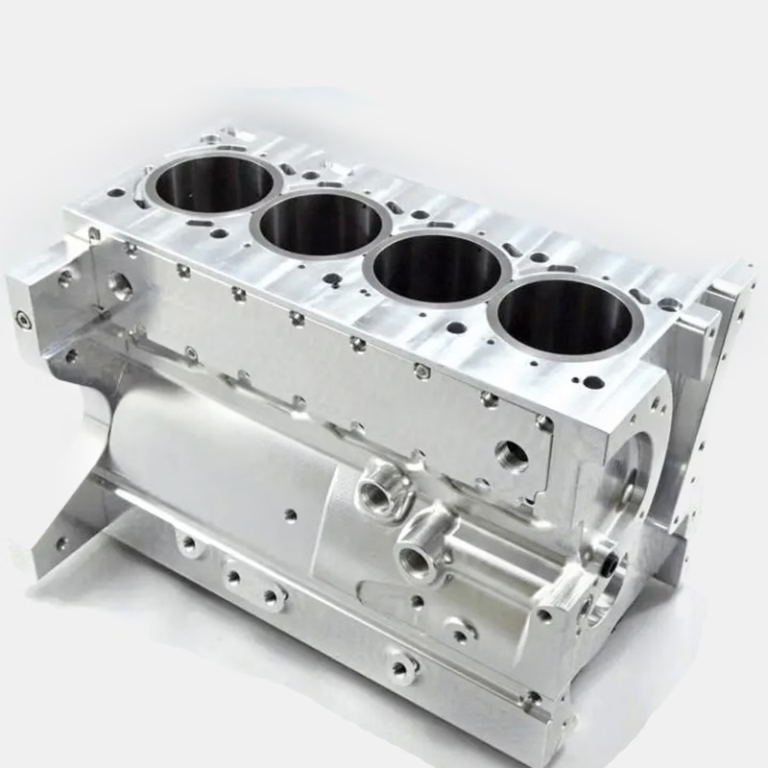
CAM platforms for cam software multi axis machining work
Ratings reflect shop-floor use on simultaneous 5-axis work, not marketing tiers.
| Platform | Toolpath style | Simulation | Best fit |
|---|---|---|---|
| Siemens NX CAM | Feature-based, integrated CAD | Machine-code verified, strong | One CAD-to-CAM seat, aerospace parts |
| Mastercam | Dynamic Motion roughing | Backplot + machine sim | Job shop mix of 3, 4 and 5 axis |
| HyperMill | 5-axis cycles purpose-built | Full machine simulation | Impellers, blisks, mold cavities |
| PowerMill | High-speed 5-axis strategies | Machine simulation built in | Deep cavities, hard tool steel |
| Fusion 360 CAM | Cloud, modular 5-axis add-on | Cloud + local simulation | Prototypes, low-volume runs |
What changes when the machine gains two rotary axes
A 3-axis mill moves the tool in X, Y and Z. Add A, B or C rotation and the tool can reach the side of a part without a second setup. That is the whole point of multi axis work: fewer setups, tighter position control, and surfaces that a straight Z approach simply cannot cut.
The catch is that the CAM system now has to solve two problems at once. It must keep the tool tip on the surface, and it must keep the machine itself out of trouble. Tool holder, spindle nose, trunnion, table, fixtures and the part all move relative to each other. A toolpath that looks correct on screen can still crash at the machine.
Most shops that fail at 5-axis work do not fail because the CAM cannot generate a path. They fail because the post-processor is wrong, the stock model is stale, or nobody checked the rotary limits before the first cut.
For reference, GreatLight runs 16 simultaneous 5-axis machining centers, 12 four-axis mills, 27 three-axis machines and 16 mill-turn centers. Those machines cut aluminium, stainless, titanium and Inconel to ±0.005 mm (±0.0002 in) when the process is set up correctly. The CAM seat is only one link in that chain.
Five checks that separate capable CAM from adequate CAM
Check one: does the toolpath engine generate true simultaneous motion, or does it just index the rotary axes and cut in 3+2? Both have a place, but only simultaneous output reaches undercuts, blended fillets and continuous contoured surfaces.
Check two: how does the system verify the cut? Backplot shows the tool centre line. Machine simulation shows the whole kinematic chain with real holder geometry and real limit switches. On a trunnion machine, you want the second kind.
Check three: can you edit the post-processor yourself? Every machine builder writes its own M-code conventions, pivot offsets and rotary unwind rules. If the post is locked and every change needs a vendor ticket, your lead time suffers.
Check four: how does it handle rest material? Complex parts are cut in stages, and the CAM must track what the previous tool actually removed, not what it was supposed to remove.
Check five: tool library and feed-and-speed data. A library tied to your real holders and inserts saves more time than any single toolpath trick.
- 1Simultaneous vs 3+2Positional work is faster to program; simultaneous work reaches geometry you cannot index to.
- 2Simulation depthMachine simulation catches holder and trunnion collisions that backplot misses.
- 3Post accessEditable posts keep you independent of the software vendor's schedule.
When each platform makes sense
Siemens NX CAM suits teams that already design in NX. The CAD and CAM share one model, so a design change propagates into the toolpath without a file translation step. It is heavy software and it costs accordingly, but for aerospace and medical parts with tight revision control it removes a whole class of errors.
Mastercam is the common choice in job shops running a mix of 3-axis, 4-axis and 5-axis work on the same floor. Dynamic Motion roughing keeps tool load steady in aluminium and mild steel, and the learning curve is shorter than the high-end packages. Its simulation is good enough for most trunnion machines.
HyperMill and PowerMill are specialist tools. HyperMill ships purpose-built 5-axis cycles for impellers, blisks and mold cavities, where the surface is defined by a swept curve rather than a simple wall. PowerMill leans toward deep cavities and hard tool steel, where high-speed 5-axis strategies protect the cutter. If your parts are mostly prismatic, both are more software than you need.
Fusion 360 CAM covers prototypes and low-volume runs. The 5-axis extension is modular, and the cloud model helps small teams. It is not the tool for a 4,000 mm gantry part or a deep hardened cavity.
Where CAM choice stops mattering
Software cannot fix a machine that is out of square, a fixture that flexes, or a tool holder with 0.02 mm of runout. We have seen shops buy a top-tier CAM seat and still scrap parts, because the stock model was never updated after the first operation.
Thermal growth matters on long cuts. A titanium part can move more during a 90-minute cycle than the CAM tolerance allows. Probing between operations, then re-cutting the datum, does more for accuracy than a finer toolpath tolerance.
The CAM also has to match the machine's control. A post that assumes a 45-degree B-axis head will not drive a machine with a Ø400 mm rotary table, even if the part geometry is identical. Post-processors are machine-specific documents, not generic exports.
Our rule of thumb: pick the CAM your programmers already know, then invest in the post-processor and the simulation model. A familiar mid-tier package with a correct post beats an unfamiliar premium package with a shipped default post.
Which one to pick
If your parts are aerospace, medical or tightly revision-controlled, pick NX CAM or HyperMill and budget for a proper post. If you run mixed 3-axis to 5-axis job-shop work, Mastercam is the safer bet. If you are prototyping, Fusion 360 CAM is enough.
FAQ: cam software multi axis machining
Does the CAM software decide whether a part can be machined at all?
No. Geometry decides that. If the tool cannot physically reach a feature, no toolpath will change it.
CAM tells you early. A good simulation will show the holder hitting the wall while the part is still a model, not a 4,000 mm casting.
Is 3+2 positioning enough for most parts?
For prismatic parts with features on several faces, yes. Indexing the rotary axes and cutting in three axes is faster to program and usually stiffer.
Simultaneous motion earns its cost on blended surfaces, undercuts, deep pockets with drafted walls, and features that must be cut in one continuous pass.
How long does it take to get a new post-processor working?
A standard trunnion or table-table post can be proven in a day or two of test cuts. A machine with unusual kinematics or a custom head takes longer.
The time goes into verifying pivot offsets, rotary unwind direction and limit handling, not into writing the file.
Can you quote a part without telling us which CAM you use?
Yes. We quote from your CAD file and a drawing, not from a CAM seat list. The DFM analysis we return within 12 hours covers reachable features, tolerances and suggested fixturing.
If a feature needs 5-axis simultaneous motion, we say so in the analysis. If it can be done in 3+2 or on a mill-turn center, we will often suggest that route instead because it is cheaper for you.
Do you inspect multi-axis parts differently?
Every part gets 100% inspection before shipment, with raw material check, in-process monitoring and final inspection. Reports are available on request.
For contoured surfaces we compare against the CAD model rather than a drawing dimension, because a 3-axis height gauge cannot describe a swept surface.
What if we only have a 3-axis machine?
Then a 5-axis CAM seat will not help. Either choose a supplier with 4-axis or 5-axis capacity, or redesign the part into features reachable from a fixed direction.
We run 27 three-axis machines, so simple parts are not pushed onto expensive 5-axis time. That keeps cost down when the geometry allows it.
Send the model and get a real answer
Upload your CAD file and we return a quotation with free DFM analysis within 12 hours. NDA available on request.
12-hour quote±0.005 mm100% inspection
More from the shop floor
We publish setup notes, tooling trials and inspection data from the factory floor.











