
Which Components Move During CNC Machining?
A moving part in a CNC machine is either cutting metal or positioning it. This page separates the two groups, lists the axes that carry them, and shows which motion you should actually hold responsible when a dimension drifts. Written for engineers and buyers who need to judge a process, not memorize a parts diagram.
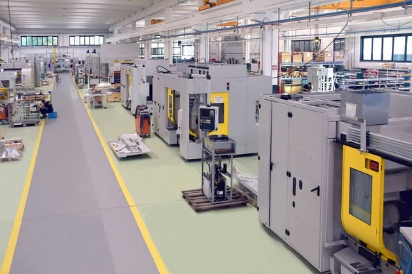
Which Components Move During CNC Machining: Motion Compared
Compare the two motion groups before you read the details below.
| Component | Type of motion | Role | Typical range |
|---|---|---|---|
| Spindle | Rotation + Z travel | Holds and spins the tool | A few hundred to 20,000+ rpm |
| Work table | Linear X, Y and Z | Carries and positions the part | Travel to 4,000 mm |
| Axis drives | Linear and rotary feed | Move slides to programmed points | Feed to about 10 m/min |
| Rotary table | A and B rotation | Tilts or indexes the part | Ø400 mm table |
| Tool changer | Rotary + linear swap | Replaces tools between steps | Seconds per tool change |
| Tailstock | Linear along Z | Supports the part on a lathe | Follows the Z slide |
The Spindle: Rotation and the Z Slide
The spindle is the only component that both spins and translates. It holds the tool in a taper or HSK interface and turns it at the programmed speed. On our 3-axis machines that speed sits anywhere from a few hundred rpm for a large face mill to well over 10,000 rpm for a 3 mm end mill in aluminium. The spindle also owns the Z motion on most vertical machines, so every plunge and every depth of cut is a spindle movement.
Rotation and Z travel behave differently, and that difference matters when you read a tolerance. Radial error in the spindle bearing shows up as a size change in the part. Axial error in the Z ball screw shows up as a depth change. If your bore is oval, look at the spindle. If your pocket floor is uneven, look at Z.
Spindle speed also sets the surface finish you can hold. On aluminium we commonly run to Ra 0.8–1.6 μm and go finer on request. Pushing the spindle past the tool manufacturer's limit buys cycle time and costs you tool life and finish. There is no free speed.
On a mill-turn center the spindle does double duty: it spins the tool and it indexes the part as a C axis. That single component then carries two tolerances at once, which is why mill-turn setups need a careful inspection plan.
- 1Radial runoutShows as bore size and roundness error.
- 2Axial floatShows as floor depth and shoulder error.
- 3Speed ceilingSet by tool diameter and material, not by the machine rating.
The Table and the Linear Axes: Positioning the Part
The table is the second moving group. On a 3-axis vertical mill it moves in X, Y and sometimes Z while the spindle stays put in X and Y. On a gantry or a large travelling-column machine the table can be static and the column moves instead. Either way, one side moves and the other is the reference, and the part sits on the moving side.
Axis drives do the work. Ball screws, rack and pinion, or linear motors all convert motor rotation into slide travel. Ball screws dominate general machining because they are stiff and repeatable. Linear motors are faster and have no backlash, but they cost more and generate heat that has to be managed. For most parts we machine in Dongguan, a good ball screw setup holds ±0.005 mm without drama.
Travel size decides what fits on the machine, not what is accurate. We run large travels of 4,000 × 400 × 150 mm, medium travels of 750 × 1,150 × 550 mm and 600 × 600 × 600 mm, and compact travels of 500 × 500 × 450 mm and 500 × 310 × 200 mm. A part that only needs 100 mm of travel does not benefit from being placed on the biggest machine in the shop.
Thermal growth is the quiet problem in this group. A ball screw that runs for two hours gets longer. On a tight part we rough, let the machine settle, then finish. Skipping that step is the most common reason a first article passes and the tenth part does not.
- 1Ball screwStiff, repeatable, the default for milling and turning.
- 2Linear motorFaster and backlash-free, higher cost and more heat.
- 3Rack and pinionFor very long travel, less precise per axis.
Rotary Axes: A and B Tables
A rotary table adds one or two rotational axes. The A axis tilts around X, the B axis tilts around Y, and a C axis spins around Z. On a true 5-axis machine the tool tip stays oriented to the surface while the table or the head rotates, so undercuts, deep pockets and compound angles get cut in one setup. We run 16 simultaneous 5-axis machining centers and a Ø400 mm rotary table for the smaller work.
The practical gain is not speed. It is fewer setups. Every time a part is unloaded and reloaded you add fixture error. A 5-axis setup removes two or three of those events, and the position of one feature relative to another stays inside the same machine coordinate system. That is usually worth more than the cycle time.
Not every part needs a rotary axis. A flat plate with holes on one face is faster and cheaper on a 3-axis machine. The rotary table earns its place when features sit on three or more faces, or when a compound angle has to be held to ±0.005 mm relative to a datum that cannot be re-established by hand.
There is a trade-off in rigidity. A tilted table puts the part further from the spindle nose and adds a rotating joint to the load path. For heavy interrupted cuts in steel, a 3-axis setup with a solid vise often cuts better. Choose the rotary axis for access, not for brute force.
- 1Use a rotary axis whenFeatures on three or more faces, or compound angles.
- 2Stay 3-axis whenOne face, high cutting load, simple geometry.
Tool Changers and Secondary Movers
The tool changer moves so the spindle does not have to. It pulls a tool from a magazine or carousel and swaps it into the spindle taper. Its motion is partly rotary, partly linear, and it happens between cuts, so it does not touch part accuracy. It touches throughput. A 20-tool magazine on a job that needs 12 tools keeps the spindle cutting; a 6-tool magazine on the same job adds minutes per part.
Secondary movers are easy to forget. The tailstock on a lathe slides along Z to support a long shaft. A bar feeder pushes stock forward. A pallet changer swaps fixtures so the machine cuts while the operator loads. None of these shape the part directly, but each one changes the setup and the cycle.
There is also the motion you cannot see: the probe. A touch probe is a moving component on a 5-axis machine. It measures a datum or a finished feature without breaking the setup, and the offset it writes goes straight into the control. On a part with a ±0.005 mm callout, probing a datum before the finish pass is often the difference between a pass and a rework.
Together these parts decide how many parts per hour come off the machine. They do not decide whether the part is correct. Keep the two questions separate and troubleshooting gets much faster.
- 1Tool changerAffects cycle time, not part geometry.
- 2ProbeAffects setup accuracy and in-process control.
- 3Pallet changerAffects spindle uptime and batch flow.
Which Motion Causes Which Problem
When a dimension drifts, the fastest route is to name the motion responsible. Taper in a deep bore points at spindle tilt or tool deflection, not at the X axis. A step between two pockets cut in the same setup points at lost motion in one axis drive or at thermal growth. A hole pattern that is correct in size and wrong in position points at the fixture or the machine coordinate system.
Repeat the cut before you change anything. If the error repeats, it is mechanical or thermal. If it moves around, it is clamping, chip packing or tool wear. That single test separates most causes, and it costs one part.
Machine choice should follow the feature list, not the other way around. Count the faces that carry toleranced features. Count the datums you cannot re-establish by hand. If both numbers are small, a 3-axis machine with a good fixture will beat a 5-axis machine on cost and usually on rigidity.
We quote from your drawing and give a free DFM analysis within 12 hours, including a note on which axes the part actually needs.
- 1Size error, round partSpindle or tool, not the table.
- 2Position error onlyFixture, datum or coordinate system.
- 3Drifts over the runThermal growth in the ball screw.
Pick the Machine by Feature Count, Not by Hype
If all toleranced features sit on one or two faces, choose a 3-axis machine with a rigid fixture. If they sit on three or more faces or on compound angles, choose a 5-axis machine and accept the slight loss of rigidity. Everything else is a detail you can fix in the setup.
Common Questions
Does the workpiece move on every CNC machine?
No. On a 3-axis vertical mill the table moves and the spindle only moves in Z. On a gantry mill the table can be fixed and the column travels. On a lathe the part rotates and the turret moves in X and Z. The rule is simple: one side is the reference and the other side moves.
Ask which side holds the datum before you approve a fixture. If the datum sits on the moving side, thermal growth shows up directly in your dimension.
How many axes does a 5-axis machine actually move at once?
A simultaneous 5-axis machine moves all five under one command, so the tool tip follows a continuous path while the part tilts. A 3+2 machine indexes to a position and then cuts with three axes.
For a compound angle held to ±0.005 mm relative to a datum, simultaneous motion is usually the safer choice. For a part with five flat faces, 3+2 indexing is faster and easier to inspect.
Which moving part limits the surface finish?
The spindle usually does, followed by the tool. Spindle runout and bearing condition set the floor on finish. Axis drives matter more for position than for finish.
As a reference, we hold Ra 1.6–3.2 μm as-machined, Ra 0.8–1.6 μm on a normal finish pass, and Ra 0.2–0.8 μm when the drawing calls for it.
Can a tool changer cause a dimensional error?
Directly, no. The tool changer swaps tools between cuts and does not touch the part. Indirectly, yes: a worn taper or a chip on a tool holder seat changes the tool length offset, and the next feature comes out at the wrong depth.
Keep the taper clean and re-check offsets after any crash. That covers most of it.
Why does the tenth part drift when the first one passed?
Heat. Ball screws, spindles and coolant warm up over the first hour or two of a run, and the machine grows. The first article is measured cold, the tenth is measured hot.
Rough the batch, let the machine settle, then finish. On tight work we also probe a datum before the finish pass so the offset follows the real machine, not the cold one.
What decides whether a part goes on a 3-axis or a 5-axis machine?
The number of faces carrying toleranced features, and the number of datums you cannot re-establish by hand. Two faces and one datum usually means 3-axis. Three or more faces, or a compound angle tied to a datum, usually means 5-axis.
Cost follows the setup count, not the axis count. Fewer setups means less fixture error and a shorter inspection list.
Send the Drawing, Get the Axis Plan
Upload your files and we return a quotation with a free DFM analysis within 12 hours, including a note on which axes the part needs and why.
12-hour quote100% inspectionNDA on request
More Machining Notes
We publish setup notes, tooling trials and inspection data from the factory floor.











