
Why Choose Custom Metal 3D Printing China: A Troubleshooting Guide
Most problems with metal additive parts come from process control, not the machine. This guide shows engineers and buyers where defects start, how to read them, and what to ask a supplier before cutting a purchase order.
In this article
- 1
- 2
- 3
- 4
- 5
- 6
- 7
Metal 3D printing defects: symptom, cause, action
Use the left column to match what you see in metrology or CT. The middle column is the usual root cause; the right column is what to change on the next build.
| Symptom | Likely cause | What to do |
|---|---|---|
| Gas porosity in a thick boss | Laser energy density too high for the section | Drop laser power 10–15%, re-run test cube |
| Cracks at the base of a support | High residual stress after fast cooling | Add stress relief before support removal |
| Edge curl on thin walls | Uneven thermal gradient across the layer | Add anchors; reduce scan speed near edges |
| Dimensional drift over 200 mm | Build plate heat soak; powder bed sink | Recheck Z calibration; cut build height |
| Rough downskin on overhangs | Unmelted powder sticking to the surface | Tilt the face; bead blast at 4–6 bar |
| Trapped powder inside channels | No escape path for the powder bed | Add two Ø3 mm drain holes per channel |
| Hardness below spec after HIP | Wrong HIP cycle for the alloy | Match cycle to Ti-6Al-4V or AlSi10Mg data |
Custom Metal 3D Printing China: What Buyers Actually Get
When engineers ask why choose custom metal 3d printing china, the honest answer starts with process control, not price. SLM and DMLS build parts layer by layer from metal powder, so the same geometry can come out dense or porous depending on laser power, scan speed, and hatch spacing. A supplier that logs those parameters per build will catch defects before shipment. One that does not will ship them to you.
The common failure modes are well known. Gas porosity shows up as round voids inside thick sections. Lack of fusion looks like flat, sharp-edged gaps between scan tracks. Both read clearly on CT, and both trace back to energy density. If a supplier cannot show you the parameter set used for your alloy, treat that as a warning sign, not a minor gap.
Post-processing decides whether an additive part is usable. Support removal, stress relief, HIP, and CNC finishing of critical interfaces all change the final dimensions. A part that measures right on the build plate can drift 0.1 mm after heat treatment. This is why we measure after finishing, not before, and why we quote finishing as part of the process rather than an optional extra.
- 1Powder traceabilityAsk for the powder lot number and sieve history. Reused powder changes flow and oxygen content.
- 2Per-build parameter logLaser power, scan speed, layer thickness, and hatch spacing should be recorded, not guessed.
- 3Finishing includedHeat treat and CNC finishing move dimensions. Plan for them from the first DFM review.
- 4Inspection after finishingFinal metrology on the finished part, not the green build, is the only number that matters.
Where the Geometry Fights the Process
Metal additive handles internal channels and organic shapes that milling cannot reach. It struggles with flat, thin, unsupported faces. A 0.5 mm wall standing 40 mm tall will curl at the top edge unless you add a rib or accept a slower scan. Design for additive means working with that limit, not ignoring it.
Overhang angle is the other hard number. Below about 45° from the build plate, downskin quality drops and support density rises. Supports are not free: they add material, build time, and a removal step that can scratch the part. Where a face must stay smooth, orient it upward or plan a CNC skim cut after printing.
Minimum feature size depends on the alloy and the machine. For AlSi10Mg on a well-tuned SLM system, we hold channels down to about Ø1 mm and walls down to 0.4 mm in low-stress areas. Titanium behaves differently because of its higher melt point and oxygen sensitivity. Do not assume one rule covers both.
Trapped powder is a silent defect. A closed internal channel with no drain path will hold powder that later escapes into a cleanroom or a hydraulic line. Add two drain holes per channel, Ø3 mm or larger, and orient them so gravity helps during support removal.
How to Vet a China Metal AM Supplier
Certifications tell you the quality system exists. ISO 9001:2015 covers general process control. IATF 16949:2016 matters if the part feeds automotive or EV production. ISO 13485:2016 is the one to check for medical devices, and ISO 27001:2022 covers how your files are stored. Ask for the certificate scope, not just the logo.
Equipment breadth matters because metal AM rarely ships alone. A printed bracket usually needs tapped holes, a flat mounting face, or a sealed bore. A supplier with both additive and subtractive capacity can finish the part in one queue. Ours runs 127 high-precision CNC machines across 7,600 m² in Dongguan, with 16 simultaneous 5-axis centers for the finishing cuts.
Metrology is where quotes differ most. A supplier that inspects 100% before shipment will catch drift that a spot-check misses. Ask what instrument is used, what the report contains, and whether the report ships with the parts. If the answer is vague, the inspection probably is too.
Confidentiality is a real concern for defense, medical, and consumer electronics work. Uploads should be encrypted, access limited, and an NDA available before you send the STEP file. We sign them on request, and we do not reuse customer geometry in samples.
- 1Match the certificate to the industryISO 9001 for general work; IATF 16949 for automotive; ISO 13485 for medical.
- 2Check the finishing queueIn-house 5-axis and EDM shorten the loop between print and finished part.
- 3Demand the inspection report100% inspection with a report on request beats a verbal assurance.
- 4Settle the NDA firstGet the agreement signed before the STEP file leaves your network.
Cost, Lead Time, and Where the Savings Come From
Metal AM cost is driven by machine time, powder, and post-processing labor. Machine time is fixed by geometry and layer count. Powder cost depends on the alloy and how much is reused. Post-processing is where two quotes for the same part can differ by 40%, because one supplier includes stress relief and CNC finishing and the other lists them as extras.
A vertically integrated supplier removes the middle layer. Aggregators add margin on top of factory pricing and add a communication hop between your engineer and the machine operator. Working directly with the factory shortens the DFM loop, which matters most when the first build reveals a warping problem.
Our quotation and free DFM analysis come back within 12 hours. Production can start within 24 hours of approval, and parts ship in 3–5 days for standard runs. There is no minimum order quantity, so a single prototype and a 10,000-part run go through the same review.
Fast turnaround does not mean skipping steps. We still run raw material checks, in-process monitoring, and final inspection. The 12-hour quote is a review commitment, not a promise that a complex titanium part will be printed overnight.
When to Print and When to Machine
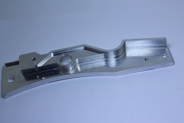
The best process for a part is often a hybrid. Print the complex internal geometry, then CNC the sealing faces, bearing bores, and threaded holes. This gives you the design freedom of additive with the tolerance and finish of 5-axis milling, without holding the whole part to ±0.005 mm on the printer.
Tolerances make the choice clear. Metal AM holds roughly ±0.1 mm on a well-tuned build, and that moves after heat treatment. If a face must sit within ±0.005 mm or reach Ra 0.2–0.8 μm, it needs a machining pass. If the feature is an internal cooling channel or a lattice, printing is the only practical route.
Some parts should not be printed at all. A simple block with three holes is cheaper and faster on a 3-axis mill. Printing it wastes powder and machine time, and the surface finish will be worse. We say so during DFM review, even when it removes work from our own additive queue.
For production volumes above a few thousand parts, casting may beat printing on unit cost. Printing still wins when the design changes often or the run is small. The decision is a cost curve, not a rule.
Step-by-Step: Getting a Clean Metal AM Part
- 1Send the STEP file and the functional calloutsList which faces seal, which bores carry a bearing, and which surfaces are cosmetic. Tolerance alone does not tell us where the part must work.
- 2Review the DFM report within 12 hoursWe flag overhangs below 45°, unsupported walls under 0.5 mm, and closed channels without drain holes. Fix these before the build, not after.
- 3Confirm the alloy and powder lotAlSi10Mg for lightweight brackets, Ti-6Al-4V for high-strength medical and aerospace parts. We record the powder lot and sieve history.
- 4Set the build orientation and supportsOrientation drives downskin quality and support volume. Where a face must stay smooth, we rotate it upward or plan a CNC skim cut.
- 5Print, then stress relieve before support removalSkipping stress relief causes cracks at support bases and warping during wire EDM. We run the cycle matched to the alloy.
- 6Machine critical interfaces on 5-axis centersSealing faces, bores, and threads are cut after printing. This is where ±0.005 mm and Ra 0.8–1.6 μm come from.
- 7Inspect 100% before shipmentRaw material check, in-process monitoring, and final inspection. Reports are available on request.
- 8Ship in 3–5 daysParts ship after inspection passes. Uploads stay secure, and an NDA is available on request.
Questions Engineers Ask Before Ordering
What tolerance can metal 3D printing hold?
As printed, expect roughly ±0.1 mm on a well-tuned SLM build, and more on tall parts because of heat soak in the build plate.
If a feature needs ±0.005 mm or a fine finish, we machine it after printing on a 5-axis center. That is how we reach Ra 0.2–0.8 μm on sealing faces.
Which alloys do you print?
AlSi10Mg for lightweight brackets and heat exchangers, Ti-6Al-4V for medical and aerospace parts, and stainless grades including 316L and 17-4PH.
Tool steel and Inconel are available for wear and high-temperature applications. Tell us the service condition and we will suggest the alloy.
How do you prevent powder from staying inside channels?
We add at least two drain holes per internal channel, Ø3 mm or larger, and orient them so gravity helps during powder removal.
Closed channels with no escape path are flagged in the DFM report. Without a drain, powder will escape later into a hydraulic line or a cleanroom.
Do you sign an NDA?
Yes. We sign an NDA on request before receiving the STEP file. Uploads are encrypted and access is limited to the engineers on the job.
We do not reuse customer geometry in samples or marketing material.
What is the minimum order quantity?
There is no minimum. A single prototype and a 10,000-part run go through the same DFM review.
Unit cost drops with volume, but the process steps do not change.
When is CNC milling a better choice than printing?
Simple blocks, plates, and turned parts are cheaper and faster on a mill, with better surface finish.
Printing wins when the part has internal channels, lattices, or organic shapes that no cutter can reach. Many parts use both.
Send Your File and Get a DFM Review
Quotation and free DFM analysis within 12 hours. Uploads are secure and confidential.
12-hour quote100% inspectionNo minimum orderNDA on request
More from GreatLight
We publish setup notes, tooling trials and inspection data from the factory floor.











