
3D Printing Starter Guide: 5 Essentials You Can't Ignore
A practical 3d printing starter 5 checklist for engineers, designers and buyers who need parts that survive real loads. Read it and you can decide which geometry should be printed, which should be machined, and where the hidden cost sits.
Five decisions that decide whether your prototype works
Each essential below ends with a rule you can apply on the next part you quote.
Know where 3D printing ends and CNC machining begins
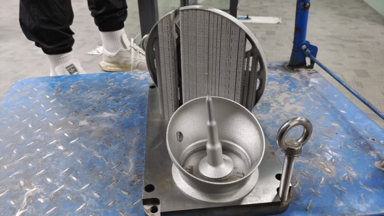
Printing wins on internal geometry. Conformal cooling channels, lattice blocks, merged sub-assemblies that would need five separate parts in machining. When the shape is the hard part, print it. Tooling cost is near zero and the first article arrives fast.
Machining wins on load path. A printed aluminium bracket can look correct and still fail in fatigue, because layer bonds and microporosity act as crack starters. Wrought billet is homogeneous in all three axes, so a 6061-T6 part that passed its static test also passes its vibration test.
Use them in sequence, not as rivals. Iterate shape, fit and assembly on the printer while the design is still moving, then switch to precision CNC machining the moment performance has to be validated. GreatLight runs both processes under one roof, so the handoff does not need a new supplier, a new DFM cycle or a new set of tolerances.
A rule that saves money: print anything that touches only air or cable routing. Machine anything that carries torque, preload or a fatigue cycle. That single line removes most of the arguments inside a design review.
- 1PrintInternal channels, lattices, merged assemblies, early fit checks.
- 2MachineLoad paths, bearing seats, sealing faces, threaded joints.
- 3BothPrint the shape, machine the critical interface.
Material selection: do not trust generic property tables
A datasheet that says "nylon" tells you almost nothing. PA12 printed by SLS, PA6 reinforced with carbon fibre and PA6 extruded into a machined block behave like three different materials. Strength, elongation and moisture uptake all move with the process, not just the polymer name.
The same trap exists in metal. A printed 316L part and a machined 316L part share a grade name and very little else. Printed metal carries porosity and a directional grain, so its fatigue limit is lower than the wrought bar stock we machine every day.
For anything structural, we ask what the part must do rather than what it must be made of. Load, temperature, chemical exposure, wear surface, weight budget. From those answers, a machined 6061-T6, 7075 or 17-4PH part is often cheaper than it looks, because it needs no post-processing to reach its final properties.
Plastics still have a place. POM and PEEK machined parts handle sliding contact and heat far better than most printed polymers, and ABS, PC or carbon fibre stock gives you a real engineering plastic at prototype quantity.
- 1Check the process, not the gradeSLS, FDM and machined stock differ in strength and anisotropy.
- 2Watch moisturePA and ABS absorb water and change dimension over weeks.
- 3Match finish to functionSliding and sealing surfaces rarely print well.
When a printed part is the right answer, and when it is not
Use this as a first screen before you send a file to either process.
| Requirement | 3D printing | CNC machining |
|---|---|---|
| Internal channels or lattice | Yes, this is the main advantage | Hard or impossible to reach |
| Fatigue or vibration load | Risk from layer bonds | Wrought billet, consistent in all axes |
| Wall thickness under 1 mm | Possible, depends on process | Often needs a redesign |
| Tolerance tighter than ±0.05 mm | Rarely holds without rework | ±0.005 mm achievable |
| Surface Ra 0.8–1.6 μm | Needs sanding or coating | Directly from the cutter |
| One-off complex shape | Fast, low setup cost | Fixtures and CAM time |
| Threaded or sealing interface | Insert or post-machine | Cut in one setup |
| Run of 10,000+ parts | Cost per part stays high | Tooling amortises, price drops |
Layer orientation and geometry: the invisible design rules
Printed parts are not isotropic. Strength differs along X, Y and Z because each layer is a bond, not a continuous grain. A bracket printed standing up can delaminate at a fraction of the load that the same bracket printed on its side carries.
Orientation is a design decision, not a slicing afterthought. If the tensile load runs across layers, rotate the part on the bed or add a machined feature to take that load. Where a printed boss meets a machined shaft, the joint should be designed so the load enters the metal.
Geometry also has process limits that CAD hides. Sharp internal corners concentrate stress in a printed part more than in a machined one, because the bond line follows the corner. A 0.5 mm fillet costs nothing to add and removes a common failure point.
Draft, minimum feature size and unsupported overhangs all change between processes. Send the model with the load direction marked, and the orientation choice becomes a conversation instead of a guess.
- 1Mark the load axisA note on the drawing is worth more than a tolerance block.
- 2Add fillets earlyCorners are where printed parts crack first.
- 3Design the metal insertLet machined features carry threads and bearings.
Surface finish and post-processing: where prototypes go to die
A printed part comes off the machine with layer lines, support scars and an open surface. For a form study that is fine. For a mating face, a seal groove or a bearing bore, it is not, and no amount of sanding will turn a rough surface into a tolerance.
This is the stage where schedules slip. Support removal, sanding, priming, coating and re-measuring add days, and each step can move a dimension. A part that measured correctly on the bed may not assemble after finishing.
Machined surfaces arrive at a defined value. We work to Ra 0.2–0.8 μm for fine finishes, Ra 0.8–1.6 μm for general high-finish work, and Ra 1.6–3.2 μm as-machined. Because the geometry is cut, not grown, the finish and the dimension come from the same setup.
A practical middle path: print the body, machine the interfaces. Bore, face and thread the surfaces that must be precise, and leave the organic geometry printed. You keep the design freedom and remove the assembly risk.
- 1Name the functional surfaceOnly the sealing, sliding and locating faces need fine finish.
- 2Budget the finishing timeSupport removal and coating are real schedule items.
- 3Machine the interfacesBores, faces and threads are cheap to cut after printing.
The true cost of ownership: the traps that do not show in a quote
The unit price on a quote is the smallest number in the comparison. Add the finishing steps, the reprints after a failed fit, the inspection time, and the engineering hours spent chasing a dimension that will not repeat.
Printed parts hide cost in iteration. Each change is cheap to print but expensive to re-qualify, because the mechanical properties shift with orientation and process settings. A stable machined process gives you the same part next month, from the same drawing, with the same inspection report.
Volume changes the answer again. There is no minimum order quantity here, so a single prototype and a 10,000-part run both go through the same quotation route. At low volume the processes are close. As volume climbs, the machined or cast route pulls ahead because setup is paid once.
The cheapest path is usually a hybrid. Print for the iterations that will be thrown away, machine the version that ships. GreatLight quotes that mix with a free DFM analysis within 12 hours, and production can start within 24 hours once the drawing is frozen.
- 1Count the iterationsReprints and re-qualification are part of the price.
- 2Count the finishingPost-processing is often 20–40% of a printed part's lead time.
- 3Count the riskA stable process is worth more than a low unit price.
Common questions from engineers and buyers
Can a printed part replace a machined one for a load-bearing bracket?
Sometimes, but the deciding factor is the load type rather than the shape. Static load on a printed bracket is often acceptable. Fatigue load is where printed metal and printed polymer both struggle, because layer bonds and porosity start cracks.
Our rule is simple: print the bracket for fit, then machine the version that sees vibration, preload or a long service cycle. A wrought 6061-T6 or 17-4PH part gives consistent properties in all three axes.
How do I choose between PA12, ABS, 316L and Ti-6Al-4V?
Start from the service condition, not the material list. PA12 and ABS suit enclosures, ducts and fit checks at room temperature. 316L covers corrosion resistance and moderate strength. Ti-6Al-4V covers weight-critical parts at higher temperature.
Then check the process. The same grade printed and machined will not give the same fatigue life, elongation or surface. If the part has a sealing face or a bearing seat, plan to machine that feature.
What tolerance can I realistically expect from each process?
On our CNC side, ±0.005 mm is achievable on critical features, with 100% inspection before shipment and reports on request. Printed parts are far looser, and the number moves with part size, orientation and material.
Treat any tight tolerance on a printed drawing as a post-machining operation, not a printing capability. Mark the critical dimensions so the quote can separate the two steps.
Does post-processing really add that much time?
It adds steps, and each step can move a dimension. Support removal, sanding, priming and coating are manual, so they scale with part size and feature count. A part can pass inspection on the bed and still fail to assemble after finishing.
Machined surfaces skip most of this. Ra 0.2–0.8 μm, Ra 0.8–1.6 μm and Ra 1.6–3.2 μm are cut directly, and the finish and the dimension come from the same setup.
Can I get both processes from one supplier?
Yes, and it removes the handoff risk. GreatLight runs custom 3D printing alongside 127 high-precision CNC machines, including 16 simultaneous 5-axis machining centers, so a printed prototype and its machined counterpart come from the same drawing and the same inspection standard.
Uploads are secure and confidential, and an NDA is available on request. Quotation and free DFM analysis come back within 12 hours.
What order should I use the two processes in?
Print first while the design is still moving. Iterate shape, fit and assembly at low cost. Freeze the geometry once the interfaces are stable.
Then machine the version that has to pass a real test. Because both routes sit under one roof, the transition needs no new supplier qualification and no re-drawn tolerance scheme.
Send the drawing and get a process recommendation
Upload your file and we will tell you which features to print, which to machine, and what the DFM analysis shows.
12-hour quote + free DFM±0.005 mm tolerance100% inspection before shipmentNDA on request









