
5 Latest 3D Printing Developments You Can't Ignore
A shop-floor view of the latest 3D printing developments that affect metal and engineering plastic parts, written for design engineers and sourcing teams. You will see what each change actually does to tolerances, material choice, and the point where printing stops and CNC starts.
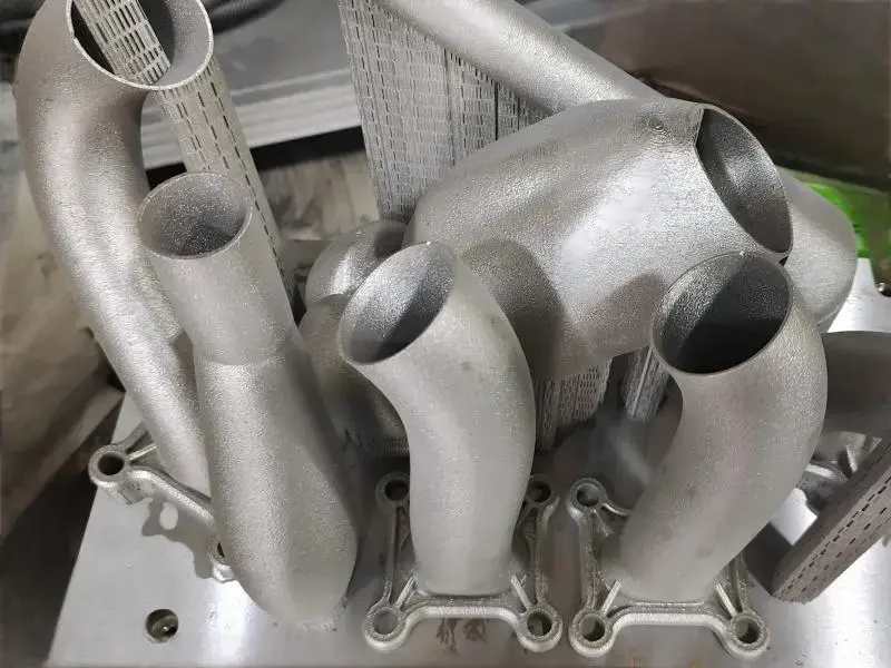
What changed, and why it matters to a part drawing
Five movements in additive manufacturing that already show up in real production quotes, not lab papers.
Large-format metal printing with in-situ monitoring
Build envelopes over 1 m are now normal on industrial powder bed fusion (SLM) and directed energy deposition (DED) systems. That size changes what you can print as one piece. Instead of welding three brackets together, you print a single near-net-shape Ti-6Al-4V or Inconel body and machine only the interfaces.
The catch is thermal history. A long build keeps the part hot for hours, so residual stress builds layer by layer. Thin walls warp, overhangs curl, and the base plate can pull the first 20 mm out of plane. In-situ monitoring is the answer the industry settled on: optical, thermal, and acoustic sensors watch each layer, and closed-loop control trims laser power or scan speed when the melt pool drifts.
For a buyer, this matters at the drawing stage. If your part is 900 mm long with a wall of 3 mm, print orientation and support strategy decide whether the blank arrives within 1 mm of nominal or 5 mm off. Ask for the build report, not just the CMM sheet.
- 1Good fitLarge single-piece housings, manifolds, brackets with internal channels
- 2Poor fitParts needing Ra 0.2–0.8 μm on every face; printing alone will not get there
- 3Ask forLayer-wise monitoring data and the as-built stress relief cycle
Multi-axis and multi-material deposition
A standard 3D printer deposits along one vertical axis. That single constraint forces supports under every overhang and limits you to stacked geometry. Robotic arm printers and 5-axis gantry systems tilt the nozzle or the table, so material can be laid down at an angle. Overhangs print without support, and the toolpath can follow a curved surface instead of stepping across it.
Multi-material heads go further. A single build can switch between a titanium core and a wear-resistant cobalt-chrome skin, or between a polymer housing and embedded conductive traces. Functionally graded parts are the practical result: hard where it rubs, tough where it bends.
This is not a general replacement for machining. Bonded interfaces between two metals rarely reach the fatigue strength of one wrought alloy. Use it where the property change is the point, not where a single material would do.
AI-driven design-to-print workflows
Print preparation used to be a manual job: orient the part, generate supports, slice, check, repeat. Modern software does most of that in one pass. It orients for the least support, predicts distortion from the thermal model, compensates the mesh before the build, and flags features that will not survive.
AI also shows up earlier, in the design itself. Generative tools propose lattice and rib layouts that meet a stiffness target with less material. For an engineer, the useful output is not a pretty shape. It is a shape that can be printed, inspected, and then machined on the faces that matter.
Keep one rule. Software proposes, the process engineer decides. A compensated mesh that nobody reviewed can hide a support contact point on a sealing face.
Production alloys and high-performance polymers
The material list for additive has moved past prototyping grades. Ti-6Al-4V, Inconel, 17-4PH, and 316L are printed as end-use parts in aerospace, energy, and medical work. On the polymer side, PEEK and carbon-fibre-filled PA now hold up in fixtures, ducts, and low-load housings where a machined part would be slower to make.
Material choice still follows the same logic as any other process. Pick by load path, temperature, and corrosion, not by what is fashionable on a printer. A printed 316L part and a machined 316L part share chemistry but not microstructure, so fatigue and elongation differ.
This is where a shop with both processes helps. We can print a near-net blank in one of these alloys, then turn and mill the critical bores so the finished part meets the same drawing as a fully machined one.
Integrated post-processing and hybrid cells
A printed part is not a finished part. It needs support removal, stress relief, base plate cut-off, and often a machined interface. Putting those steps in one cell, with printing and 5-axis machining side by side, cuts the handling and the queue time between operations.
The hybrid workflow is simple to state. Additive builds the complex internal geometry and the near-net shape. A 5-axis machining center then cuts the mating faces, threaded holes, and high-tolerance features. On our 5-axis centers we hold ±0.005 mm (±0.0002 in) on those finished features, which is what lets a printed part bolt to a legacy component.
Two numbers tell you when this pays off. First, the tolerance the interface needs. Second, the volume. Below a few hundred parts a year, hybrid usually wins on tooling cost. Above that, compare against die casting or a fully machined design.
When to print, when to machine, when to do both
Use this as a first filter before you send a drawing.
| Part situation | Print only | Print + CNC | CNC only |
|---|---|---|---|
| Internal channels or lattice | Yes | Yes | Not feasible |
| Tolerance tighter than ±0.05 mm | No | Yes | Yes |
| Sealing or mating face | Risky | Yes | Yes |
| One-off prototype | Often | Sometimes | Yes |
| 10,000+ identical parts | No | Compare | Yes |
| Large thin-wall body | With support study | Yes | Hard to hold |
What to watch before you commit a design
Three risks repeat across every additive project we quote. Anisotropy is the first. A printed part is stronger along the layer plane than across it, so a load path that runs vertically through the build loses strength. Rotate the build, or change the material, or machine the part.
The second is inspection access. A closed internal channel cannot be measured with a touch probe. If the channel is functional, agree on CT scanning or a flow test before the first build, not after.
The third is the cost of a failed build. A 40-hour metal print that warps is a write-off. That is why we ask for the tolerance callouts and the load path up front, and why the DFM review happens before the quote, not after.
- 1AnisotropyLayer direction sets fatigue life; align it with the load
- 2Hidden featuresAgree on CT or flow testing for internal channels
- 3Build failureLong metal builds carry real scrap cost; review orientation first
Questions engineers ask us
Can a 3D printed part hold ±0.005 mm?
Not as printed. Metal powder bed fusion typically lands within a few tenths of a millimetre on a good day, and less on thin walls.
We print the near-net blank, then machine the critical faces on a 5-axis center to ±0.005 mm. That combination is what gets a printed part onto a mating surface with a legacy component.
Which materials can you print and then machine?
We work with titanium grades including TA1, TA2, and TC4 (Ti-6Al-4V), Inconel, stainless including 316L and 17-4PH, and aluminium alloys.
For plastics, PEEK, PA, and carbon-fibre-filled grades are available. Finishing after machining covers anodizing, plating, powder coating, bead blasting, and laser marking.
How do you decide the print orientation?
Orientation follows the load path and the machined faces. We want the layer plane to carry the main stress and the critical bores to sit where a 5-axis tool can reach them.
Support contact points are kept off sealing faces. If that is not possible, we add machining stock and cut the face afterwards.
Is there a minimum order quantity for a hybrid print-and-machine job?
No. We run from one prototype to 10,000+ part runs.
For a single prototype the DFM review and quotation come back within 12 hours, and production can start within 24 hours. Typical parts ship in 3–5 days.
What certifications cover a printed and machined part?
Our quality system holds ISO 9001:2015, IATF 16949:2016, ISO 13485:2016, and ISO 27001:2022.
Every part gets 100% inspection before shipment, covering raw material check, in-process monitoring, and final inspection. Reports are available on request.
Will you sign an NDA before we share drawings?
Yes. Uploads are secure and confidential, and we can sign an NDA on request before you send files.
If the design is still early, send a simplified model with the critical tolerances marked and we can start the DFM review from that.
Send a drawing, get a print-or-machine answer
We review your part, tell you whether additive, CNC, or both is the right route, and quote it.
12-hour quote and DFM±0.005 mm finishing100% inspectionNDA on request









