
3D Printing With Fusion 360: 7 Essential Tips to Master
A working guide for engineers who model in Fusion 360 and send files to a printer or a machine shop. It covers the seven decisions that most often decide whether a part prints clean the first time. Read it and you can judge your own model before anyone cuts material.
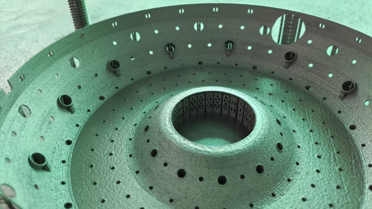
Fusion 360 Gives You Two Toolboxes, and Both Have Rules
A good print starts in the design tree, not in the slicer.
Design for the Additive Process, Not the CAD Geometry
Most engineers learn to model for milling. That habit shows up as sharp internal corners, uniform wall thickness, deep pockets with no tool access, and bosses that only a 3 mm end mill could reach. Send that same model to an FDM or SLM machine and the problems move rather than disappear. Corners become stress risers, thin walls warp, and trapped volumes hold powder or resin you cannot remove.
Think in layers while you sketch. A wall that prints well is usually thicker than a machined wall would be, and it changes along the build direction. Where a milled part wants a sharp internal corner, a printed part wants a small radius so the nozzle or laser does not leave a void. Wall thickness matters too: keep it a multiple of the extrusion width, or the slicer drops one pass and the wall ends up porous.
Before you export, run the section analysis across the part. Check the thinnest rib, the smallest hole, and any cavity that will trap material. A short check here costs two minutes. Finding the same fault after a 14-hour build costs a day.
- 1Minimum wallSet per process, then hold it everywhere on the part.
- 2Trapped volumeLeave at least one 3–5 mm opening per enclosed cavity.
- 3Sharp cornersAdd a radius that the nozzle or laser can actually follow.
- 4Section checkScan the thinnest features before export, not after.
Move Between Solid and Mesh on Purpose, and Orient for Load
Fusion 360 holds two worldviews at once. The parametric solid environment gives you history, constraints, and clean edges. The mesh workspace gives you direct control over triangles, which is what a printer actually consumes. Engineers who stay in one workspace tend to fight the other. A sculpted surface made in mesh is painful to dimension in solid. A bracket built from sketches becomes brittle to edit once it is converted to mesh.
Pick the workspace by what the feature must do. Load paths, mating faces, and anything that needs a tolerance callout belong in solid. Organic external form, lattice skins, and imported scan data belong in mesh. Convert once, near the end, and keep a solid copy of the master model so a later revision does not start from triangles.
Build orientation is a design decision, not a slicer default. Layer direction sets anisotropy: a part printed flat is weak across the layers and strong within them. On a bracket loaded in bending, orient so the layers run along the tensile side. On a part that must seal, keep layer lines off the sealing face. Mark the intended orientation in the model so the shop does not guess.
Every orientation trades support volume against surface finish and print time. A face that touches the build plate comes out clean. A face that needs support comes out rough and may need secondary work. Decide which faces matter, then let the rest land where support is cheapest.
- 1Solid workspaceMating faces, tolerances, load-bearing features.
- 2Mesh workspaceOrganic form, lattices, imported scan geometry.
- 3OrientationLayer direction should follow the tensile load path.
- 4Clean facesKeep supported faces away from sealing surfaces.
Treat Supports as a Design Task, and Set Clearances for the Process
Supports are often left to the slicer. That is where prints fail quietly. A default support pattern can fuse to the part, block a critical face, or leave a witness mark you then have to sand. Treat support as a feature you design. Add breakaway tabs where a face must stay flat. Chamfer the underside of an overhang so the first layer has something to sit on.
Angles decide whether support is needed at all. Most FDM machines hold an overhang near 45° from vertical without help. Below that, the extrusion sags. SLM is different: the powder bed supports the melt pool, so overhangs down to roughly 30–40° often print without added structure, though heat distortion becomes the limiting factor. Set the threshold per process, not once for the whole shop.
Clearances are where printed parts and machined parts diverge most. A printed hole comes out undersized, and the shrink varies with material, wall thickness, and orientation. A press fit that works on a machined aluminum boss will seize on a printed one. Model a test coupon with the same wall thickness as the real part and measure it before you commit to the assembly.
For anything that must mate with a machined component, we usually leave machining stock on the printed part. Print it 0.3–0.5 mm oversize on the critical faces, then face or bore them on a CNC. That split keeps the printed geometry cheap and the tolerance where it belongs.
- 1Overhang limitAround 45° for FDM, 30–40° for SLM in many cases.
- 2Breakaway tabsDesign flat faces so support does not touch them.
- 3Test couponPrint the real wall thickness before trusting a fit.
- 4Hybrid stockLeave 0.3–0.5 mm on faces that will be machined.
Process Behavior That Changes Your Fusion 360 Model
Working ranges from production. Tune them for your machine and material.
| Process | Wall guidance | Overhang without support | Typical use |
|---|---|---|---|
| FDM | 2–3× nozzle diameter | About 45° from vertical | Enclosures, fixtures, large shells |
| SLA / DLP | 1.0–2.0 mm | About 30° from vertical | Fine detail, smooth skins, small parts |
| SLS / MJF | 0.8–1.5 mm | Powder bed supports most geometry | Ducts, living hinges, short runs |
| SLM metal | 0.4–1.0 mm | 30–40°, watch heat distortion | Load-bearing metal prototypes |
| CNC from solid | As thin as 0.5 mm in aluminum | Not applicable | Tight tolerances, sealing faces |
Earn the Right to Print, and Know When Not To
Simulation and generative studies are useful when they answer a specific question. A static stress study tells you whether the printed wall will hold before you spend a build. A generative study gives you a shape to react to, not a shape to ship. Both are only as good as the loads and constraints you type in. Bad boundary conditions produce confident, wrong output.
Use them to close a decision. If the study shows a safety factor near 1.0 on the printed version, change the design or change the process. If it shows 4.0, you are carrying material you do not need. Either result saves money. A study that confirms what you already assumed is not worth the setup time.
Not every part should be printed. A printed prototype gets you a fit check, a form review, and a conversation with the customer. A machined part gets you ±0.005 mm, a real surface finish, and material properties you can put in a drawing. When the geometry needs a sealing face, a threaded port, or a bearing bore, print the body and machine those features.
We see this split constantly. A bracket prints in a day and then gets its mounting faces and bores finished on a 5-axis mill. The customer keeps the fast, cheap iteration and still gets a part that measures. That is the hybrid route, and it usually beats committing to one process for the whole geometry.
- 1SimulationUse it to close a decision, not to decorate a report.
- 2Safety factorBelow 2.0 on a printed part, redesign or re-process.
- 3Machine the interfacesSealing faces, threads, and bores belong on a CNC.
- 4Hybrid buildPrint the body, machine the critical features.
Common Questions
Why does my Fusion 360 hole come out undersized when I print it?
Printed holes shrink as the material cools or cures, and the amount depends on wall thickness, material, and build orientation. A 6 mm hole can close by 0.1–0.3 mm on FDM and less on SLA.
Model a coupon with the same wall thickness as the real part, measure it, and apply that offset to the hole diameter in the model. For holes that must mate with a machined shaft, leave stock and bore them on a CNC instead.
Should I convert my solid model to mesh before exporting to the slicer?
Most slicers accept STEP or the native solid directly, so you do not need to convert. Converting early throws away the parametric history and makes later edits harder.
Convert only when the geometry genuinely needs direct triangle control, such as a lattice or an imported scan. Keep a solid master copy in the project so a revision does not start from mesh triangles.
How do I decide build orientation in Fusion 360?
Start from the load path. Layers bond well within a plane and poorly across it, so put the tensile side of a bending part along the layer direction rather than across it.
Then check surfaces. Faces that touch the build plate come out clean, and supported faces come out rough. Keep supports away from sealing faces and mating surfaces, and record the intended orientation in the model.
When should I machine a printed part instead of printing the whole thing?
Machine the features that carry tolerance. Sealing faces, threaded ports, bearing bores, and any surface with a flatness or finish callout are poor candidates for printing.
A common route is to print the body for form and fit, leave 0.3–0.5 mm on the critical faces, then finish those faces on a 3-axis or 5-axis mill. You keep fast iteration and still get a measurable part.
What wall thickness should I use for a printed enclosure?
It depends on the process. FDM usually needs 2–3 times the nozzle diameter so the slicer does not drop a pass. SLA handles 1.0–2.0 mm, and SLS or MJF holds 0.8–1.5 mm.
Match the wall to the load, not to the drawing habit from machining. Uniform thickness prints and cools better than a mix of thick bosses and thin skins on the same part.
Can GreatLight review my Fusion 360 file before I commit to a process?
Yes. Send the STEP or native file and we return a DFM analysis with the quotation, typically within 12 hours. We flag thin walls, trapped volumes, and features that will not hold tolerance as printed.
If the part should be machined or built as a hybrid, we say so in the same review. Uploads stay confidential, and an NDA is available on request.
Send the Model, Get a Straight Answer on Process
Upload your Fusion 360 file and we will tell you what to print, what to machine, and what to change.
DFM review in 12 hoursNo minimum order quantity100% inspection before shipment









