
7 Essential CNCkad 12 Tips to Master CNC Programming
A shop-floor guide for programmers and process engineers who already know the basics of CAM and want fewer surprises at the machine. Each tip covers what the setting does, which parts it suits, and when it is not worth the setup time. Read it before your next family of parts or 5-axis job.
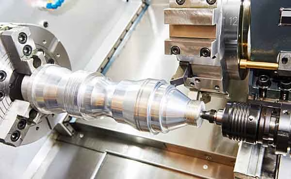
Seven tips, ranked by what they save you
Feature recognition first, tool paths second, then the checks that keep a program from stopping the spindle.
Let Feature Recognition Do the First Pass
Import a STEP file and CNCkad 12 will look for pockets, holes, slots, bosses, and 3D contours on its own. A part with twenty M6 tapped holes becomes one feature set instead of twenty manual picks. The time saving is real, but the point is consistency: every hole gets the same feed, speed, and depth, so nothing gets missed on a revision.
Run the recognition wizard before you draw a single tool path. Then open the feature tree and check it. Blends, undercuts, and shallow counterbores are the usual mistakes. Tighten the minimum hole depth or the pocket wall angle until the selection matches the drawing. Two or three minutes here will save 30 to 45 minutes of manual picking on a mid-size part.
Rough with Adaptive Clearing, Not Zigzag
High-speed machining is not about spindle RPM. It is about keeping a steady chip load and avoiding sudden jumps in tool engagement. Adaptive clearing holds a constant radial engagement angle, usually 10 to 20 percent of the tool diameter, so the cutting edge sees the same load through the whole pass.
A conventional path spikes the engagement angle the moment it enters a corner. Chatter follows, then deflection, then a broken tool. Dynamic adjustment of the path keeps chip thickness even. You can run feeds two to three times higher than conventional roughing, and the cutter lasts longer.
This strategy is worth the extra setup on deep pockets in 6061, 7075, and 17-4PH. It is a poor fit for thin-wall parts under 1.5 mm, where the tool pressure still moves the wall. Leave those for a light finishing strategy instead.
3D Tool Compensation and Collision Checking
Use 3D tool compensation when the geometry will not sit still. Impellers, turbine blades, and mold cavities with draft angles need the offset applied along the surface normal rather than in a flat plane. CNCkad 12 handles this through the surface offset method, which keeps the contact point correct as the tool tilts.
Compensation only works if the tool model is honest. Enter the real holder, the real collet, and the real stick-out. A 12 mm cutter in a 20 mm holder at 60 mm stick-out will hit a wall that a stubby setup clears.
Collision checking should run on the whole job, not just the finishing pass. Rapid moves between features are where most crashes happen. Set a clearance plane 5 to 10 mm above the stock, then let the software verify every retract. On a 5-axis job, check the rotary table envelope as well as the spindle.
Template-Based Programming for Families of Parts
A family of parts shares geometry and differs in a few dimensions. Brackets, manifold plates, and housing covers are typical. Build the operation sequence once, save it as a template, and drive the new sizes from a parameter table.
The template should carry the tool list, the speeds and feeds, the coolant settings, and the inspection notes. When a new revision arrives, you swap the model and the parameter values. The sequence stays put.
Template discipline pays off in two ways. Programming time drops to minutes instead of hours, and the shop gets the same result from any programmer on shift. Keep the template library small. Ten well-maintained templates beat sixty that nobody trusts.
Finishing Passes and Tool Wear
Finishing decides whether the part meets the print. Cross-hatching the final pass, with the second direction at 45 to 90 degrees to the first, breaks up the scallop pattern and reduces directional witness marks. On Ra 0.8–1.6 μm work, a 0.1 to 0.2 mm stepover with a small nose radius usually gets there.
Cross-hatching costs cycle time. Skip it on as-machined surfaces at Ra 1.6–3.2 μm and on non-functional faces. Save it for sealing faces, bearing seats, and sliding surfaces.
Tool wear monitoring belongs in the post-processor. Map the wear offset to the tool number and let the program apply the compensation from the measured value. If the offset moves past a set limit, the program should stop and call for a tool change instead of pushing a worn cutter through a finishing pass. Measure a sample part every 20 to 30 cycles on long runs and feed the numbers back.
Which Setting Fits Which Job
Match the strategy to the part before you start cutting.
| Strategy | Best suited to | Skip it when |
|---|---|---|
| Adaptive clearing | Deep pockets, hard alloys, long roughing runs | Thin walls under 1.5 mm |
| 3D tool compensation | Blades, impellers, drafted mold cavities | Flat 2.5D profiles |
| Collision checking | 5-axis work, deep cavities, long holders | Simple plate drilling |
| Templates | Brackets, covers, families of parts | One-off prototype geometry |
| Cross-hatch finishing | Sealing faces, bearing seats, Ra 0.8–1.6 μm | Non-functional as-machined faces |
| Wear offsets in post | Runs over 100 parts, hard materials | Single-digit batch sizes |
Programming Questions We Get Asked
Does adaptive clearing always beat a conventional roughing path?
No. It wins where the tool spends time in deep pockets or hard material, because the engagement angle stays even. On a shallow plate with open geometry, a plain offset path is faster to program and cuts just as well.
The deciding factor is corner engagement. If the path will enter tight internal corners at full radial width, switch to adaptive. If not, keep it simple.
How much stock should I leave after roughing?
For 6061 aluminium, 0.3 to 0.5 mm on walls and floors gives a clean finishing pass. Stainless and titanium need less, around 0.2 to 0.3 mm, because the finishing tool will work-harden a thick layer.
Leave extra only where the roughing tool deflects. Measure the first part and adjust the table instead of guessing.
When is template programming not worth the effort?
When the parts are true one-offs with no shared features. Building a template for a single bracket wastes more time than it saves.
The break-even sits around three or four similar parts. Below that, program each job directly.
Can collision checking slow down a large program?
Yes, on jobs with thousands of small moves. Run the full check on a 5-axis or deep-cavity job, and a rapid-move-only check on simple 3-axis work.
Turn the check off for the finishing pass only if the tool and holder are already proven on that geometry.
How often should tool wear offsets be updated?
On long runs, check a sample part every 20 to 30 cycles and update the offset from the measured size. On short runs, verify at the start and end of the batch.
Set a hard limit in the program so a worn tool triggers a stop rather than a scrapped part.
What tolerance can be held after these steps?
With a stable setup and in-process checks, our machines hold ±0.005 mm on critical features. Surface finish lands at Ra 0.8–1.6 μm on a normal finishing pass, or Ra 0.2–0.8 μm with additional lapping or polishing.
Every part is inspected before shipment, and reports are available on request.
Send Us the Part, We Will Check the Program
Upload a STEP file and our engineers return a quotation with a free DFM analysis within 12 hours. No minimum order quantity, from one prototype to 10,000+ parts.
12-hour quote100% inspectionNDA on request±0.005 mm









