
01
The print looks fine, then the thread strips
SLA resin taps badly and SLS nylon holds a thread only in thick walls. If the part needs M3 threads under load, printing is the wrong call. We machine those features instead.
We print prototypes in SLA, SLS and metal, then machine the same geometry on 127 CNC machines when the design locks. One supplier from first sample to 10,000-part runs.
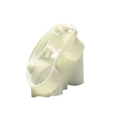
Most 3D printing complaints come from picking the process before the geometry.
SLA resin taps badly and SLS nylon holds a thread only in thick walls. If the part needs M3 threads under load, printing is the wrong call. We machine those features instead.
As-printed surfaces sit around Ra 8–16 μm with visible stair-stepping. A gasket face or O-ring groove printed flat will leak. Plan a machined face or a post-finish step.
A resin model can pass a fit check and still fail in service, because the printed material is not the material you will ship. Test on the real alloy.
Open shells and zero-thickness walls stall a quote for days. One DFM pass before printing saves a rebuild.
We treat 3D printing technology as a step in the route, not the whole route.
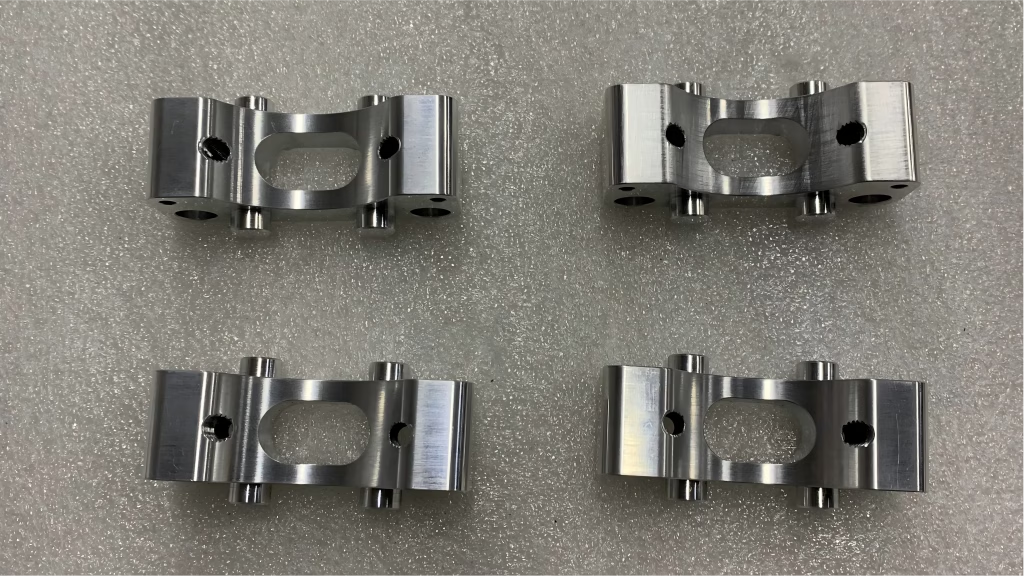
3D printing is additive: a head or laser lays down material layer by layer from a CAD file, so there is no mold and no block of stock to remove. Setup cost is close to zero, which is why the first unit is cheap and the thousandth unit is not.
We use it where it wins. SLA gives a smooth surface for form-and-fit checks and clear parts. SLS builds tough nylon parts with living hinges and snap fits, and it handles internal channels that a cutter cannot reach. Metal printing suits lattice and conformal-cooling geometry that would need many setups on a mill.
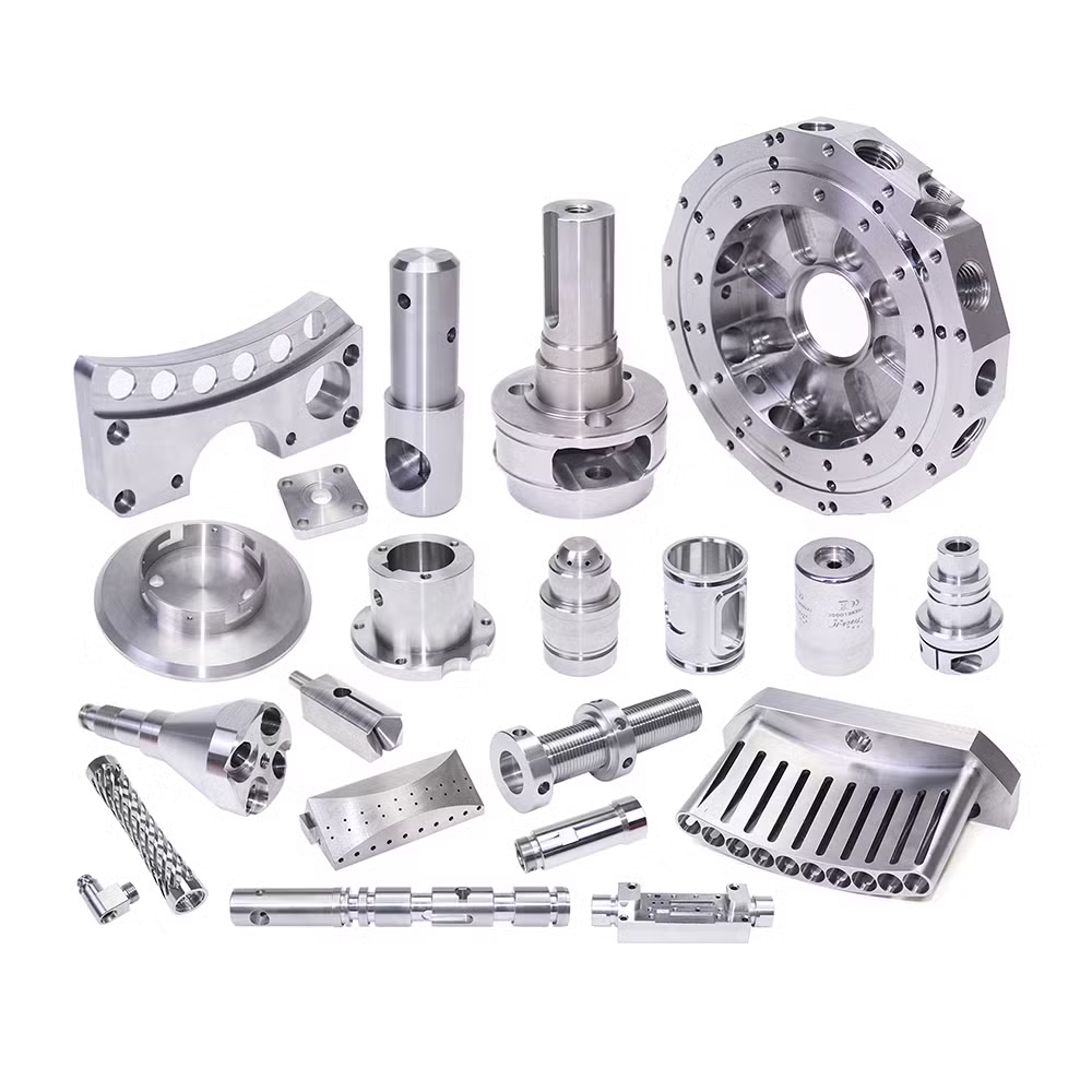
Printed parts are anisotropic. SLS nylon is weaker across the layer direction than along it, and resin creeps under sustained load. Anything that carries a load, seals a fluid, or takes a thread insert usually belongs on a CNC machine.
That switch is where we add the most value. The same shop that printed your sample machines the production part to ±0.005 mm with finishes from Ra 0.2–0.8 μm, so tolerances and datums do not get renegotiated between two vendors. We quote both routes side by side and tell you which one the geometry actually needs.
Use this as a first filter. Geometry and load decide, not the price sheet.
| Requirement | 3D printing | CNC machining |
|---|---|---|
| Surface finish | Ra 8–16 μm as built | Ra 0.2–3.2 μm |
| Tolerance | ±0.1 mm typical | ±0.005 mm |
| Wall thickness | 0.8 mm and up | 0.5 mm and up, rigid |
| Best batch size | 1 to 50 units | 1 to 10,000+ units |
| Threads | Inserts or coarse only | Cut threads, all sizes |
| Material choice | Resin, nylon, metal powder | 40+ alloys and plastics |
| Lead time | 3–5 days | 3–5 days after DFM |
| Design changes | Free until you cut | New program per revision |
SLA, SLS and metal printing for prototypes, jigs and low-volume functional parts, quoted from your STEP or STL file.
Printed or machined samples in days so a design review happens on a real part, not a screen.
16 simultaneous 5-axis centers for contoured surfaces, deep pockets and single-setup datums.
27 three-axis machines, 12 four-axis mills and 16 mill-turn centers up to 4,000 mm.
Urethane copies from a printed master when you need 20 to 50 look-and-feel units in production resin.
Anodizing, plating, powder coating, bead blasting and laser marking on printed and machined parts.
| Item | Range | Notes |
|---|---|---|
| Maximum part size | 4,000 mm | Larger parts split and joined |
| Machining tolerance | ±0.005 mm | ±0.0002 in |
| Fine finish | Ra 0.2–0.8 μm | Polished and lapped faces |
| Standard finish | Ra 1.6–3.2 μm | As machined |
| Materials | 40+ grades | Aluminium, stainless, titanium, PEEK, nylon |
| Order quantity | 1 to 10,000+ | No minimum order quantity |
| Inspection | 100% before shipment | Reports on request |
| Certifications | ISO 9001, IATF 16949, ISO 13485, ISO 27001 | Audited annually |
Critical dimensions verified against the drawing, with inspection reports available on request.
You get a price, a lead time and a DFM note on wall thickness or tool reach within 12 hours.
Once the drawing is released and material is confirmed, machining can begin the next working day.
Raw material check, in-process monitoring and final inspection on every order.
6061-T6, 316L, 17-4PH, TC4, Inconel, PEEK and carbon fibre among the standard list.
Uploads stay private, and a signed non-disclosure agreement is available on request.
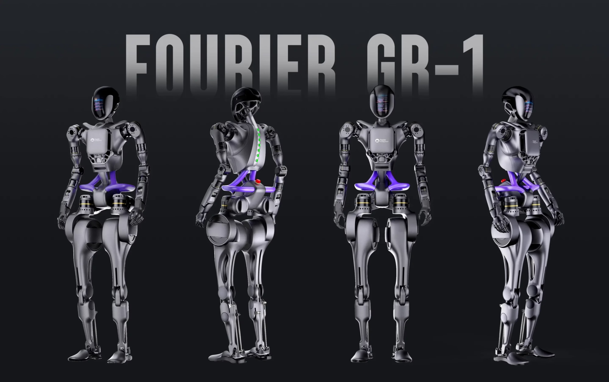
Printed joint housings for motion checks, then machined aluminium links for the build.

Bracket prototypes in SLS nylon, production parts in 6061-T6 with IATF 16949 process control.
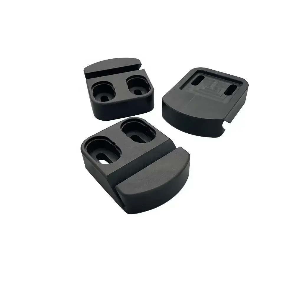
Printed fixtures for trial fits, machined 316L parts with full traceability.

Printed enclosures for board fit, then milled and anodized housings for the pilot run.
A slicer cuts the CAD model into layers, usually 0.05–0.2 mm thick, and writes a toolpath for each one. The machine then stacks and fuses those layers, either by curing resin with a laser, sintering powder, or melting filament and metal powder.
Because material is added instead of removed, internal channels, lattices and undercuts that would need several CNC setups come out in one build. The trade-off is surface finish and material properties across the layer direction.
±0.1 mm on a well-oriented SLA or SLS part is realistic, and ±0.3 mm on long thin sections where shrinkage and warping pull the geometry. Metal printing lands in a similar band after support removal.
If the drawing calls for ±0.005 mm, printing will not hold it. We print the sample and machine the feature, or machine the whole part.
Anything that seals a fluid, carries a sustained load, or needs a fine thread. Layer lines give a leak path, printed threads strip under torque, and resin creeps over time.
Bearing bores, hydraulic faces and press fits also belong on a mill or lathe. We flag these in the DFM note before you commit to a process.
Yes, in powder-bed metal for lattice and conformal-cooling geometry. We also machine the same alloys, so a printed prototype in TC4 or 17-4PH can be followed by a machined production part in the same grade.
Tell us the load case and we will say whether printing or machining is the better route.
The geometry usually survives; the material and tolerances do not. A printed part is isotropic in the build plane only, and its surface is rougher than a machined face.
In practice we keep the design intent, adjust wall thickness and add machining allowance on critical faces, then cut the production part to ±0.005 mm.
A STEP file for machining and an STL or 3MF for printing, plus a 2D drawing if any dimension is toleranced. Note the critical faces and the finish.
We return a price, a lead time and a DFM analysis within 12 hours. Files stay confidential, and an NDA is available on request.
It depends on part size and feature count, but printing usually stops paying above roughly 50 units, once per-part machine time and setup dominate the cost.
We quote both routes on the same RFQ so you can see the crossover point for your geometry instead of guessing.
Yes. Printed and machined parts both go through the same finishing line: anodizing, plating, powder coating, bead blasting, polishing and laser marking.
Laser marking needs a minimum character height of 1.5 mm. Ask for it on the drawing so the marking sits on a flat face.
Upload your CAD and we will come back with a process recommendation, a quote and a DFM note within 12 hours.
12-hour quote100% inspectionNo minimum orderNDA on request
Trusted by engineers and manufacturers worldwide










Upload your 3D model or 2D drawing and get a quotation with a free DFM analysis. Maximum processing size 4,000 mm.
CNC Metals 13 grades
CNC Plastics 10 grades
Machines & processes 12 options
Surface & post-processing 10 options
Material: not selected Machine: not selected Post-process: not selected
Fill in this short form and we'll open WhatsApp with your message ready to send. We only use these details to reply to you.
Nothing is sent until you press send inside WhatsApp.