
5 Essential Secrets of the CNC 1830 Pro to Maximize Your Machining Efficiency
A process engineer's look at why a large-envelope gantry-style machine behaves differently from a 40-taper VMC, and which five decisions actually move cycle time, scrap rate, and repeatability. Written for design engineers and sourcing teams who need to judge whether a part belongs on this class of machine.
In this article
- 1
- 2
- 3
- 4
- 5
- 6
- 7
Key takeaways
The CNC 1830 Pro Rewards Toolpaths Built for Large Travels
A machine with a long X travel and a heavy gantry structure does not respond to toolpaths the same way a compact VMC does. The mass is higher, so direction changes cost more time, and the spindle spends more of the program moving through air if the CAM strategy was written for a small envelope. Default pocketing routines assume the tool is rarely far from the cut. On a 4,000 mm envelope, that assumption breaks down quickly.
The practical fix is to sort operations by tool diameter and never re-enter a region a larger tool already cleared. Adaptive or trochoidal clearing keeps radial engagement constant, typically 8–12% of tool diameter, which spreads heat along the flute instead of concentrating it at the tip. On aluminium 6061 and 7075, that usually means higher feed per tooth with the same spindle load.
Rest machining matters more here than on a small machine. If a Ø16 mm tool clears a pocket and a Ø6 mm tool follows, the second toolpath should only touch the corners the first tool could not reach. Without that filter, the small tool recuts the whole cavity at a fraction of the material removal rate. The cycle time difference on a 300 mm deep pocket is measured in tens of minutes, not seconds.
One caution: adaptive paths generate more code. A simple pocket that took 4,000 lines with conventional offsets can take 40,000 lines with a trochoidal strategy. Check that the control's look-ahead buffer can handle it. If the machine stutters on short segments, the theoretical efficiency gain disappears in acc/dec losses.
- 1Sort by tool sizeLarge tools first, small tools only in corners.
- 2Target 8–12% radial engagementKeeps chip thinning predictable on deep cuts.
- 3Watch block countHigh-feed trochoidal paths can starve older look-ahead buffers.
Workholding Sets the Tolerance Band Before the First Cut
Engineers often quote ±0.005 mm and then fixture the part with two toe clamps and a vise stop. The machine can hold that number. The setup cannot. On a large table, the lever arm between the clamp and the cutting zone is long, and a 0.02 mm deflection at the clamp becomes 0.05 mm at the far end of the part. That is the difference between a passing first article and a rework loop.
The fix is to think about force paths, not just clamp locations. A part should be supported directly under the cut, or as close to it as geometry allows. For thin-walled aluminium housings, that often means a sacrificial backing plate or a low-melt fixturing alloy rather than more clamp pressure. More pressure on a thin wall moves the wall, it does not hold it.
Repeatability comes from locating features that do not change between operations. A three-point datum system with a primary plane, a secondary edge, and a tertiary pin gives the operator a deterministic setup every time. When the same datums are used in CAD, in the fixture design, and in the inspection report, the tolerance stack stays closed and the second operation aligns with the first.
On the CNC 1830 Pro class of machine, fixture weight also matters. A 200 kg fixture on a moving table consumes acceleration budget. Lightening the fixture with ribbed aluminium plate instead of solid steel block often improves cycle time without touching the toolpath at all.
- 1Support under the cutA clamp 200 mm away does not stiffen the cutting zone.
- 2Use one datum setCAD, fixture, and inspection should share the same three datums.
- 3Weigh the fixtureTable mass affects acceleration on long travels.
In-Process Probing Turns Thermal Drift into a Known Number
A spindle that has run for three hours at 12,000 rpm is not the same spindle that was warm-up checked at 8:00 am. The growth is small, often 5–15 μm on the Z axis, but on a ±0.005 mm part that is the whole tolerance. Static offsets set at the start of the shift cannot compensate for a change that happens after the shift is underway.
In-process probing changes the sequence. Instead of measuring after the part comes off, the machine touches a known reference surface between operations and updates the work offset. The measurement takes 20–40 seconds. The alternative is scrapping a part that took two hours to reach that point.
The same logic applies to tool wear. A touch-off probe on the tool setter before a finishing pass catches a worn insert before it burns the surface finish. On Ra 0.8–1.6 μm requirements, a 0.01 mm wear land is visible. On Ra 0.2–0.8 μm, it is a rejection.
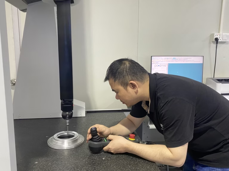
Probing is not a substitute for a CMM report. It is a process control tool. The CMM confirms the part; the probe keeps the process inside the band where the CMM will pass it. Confusing the two roles leads to either over-inspection or false confidence.
- 1Probe between operationsUpdate work offsets while the part is still in the fixture.
- 2Check tools before finishingA worn edge shows up first in surface finish.
- 3Keep the CMM separateProbing controls the process; the CMM verifies the part.
Chip Management Is a Thermal Problem, Not a Housekeeping Task
Recutting a chip takes more energy than cutting virgin material. The chip has already been work-hardened by the first pass, and it carries heat back into the cut. On stainless 316L and 17-4PH, that shows up as a sudden jump in edge temperature and a matching drop in tool life. The coolant flow rate did not change. The chip load on the edge did.
Through-spindle coolant at 40–70 bar solves this on deep pockets and long-reach tools by pushing chips out of the cut instead of washing them around inside it. On a large envelope, the alternative is a chip pile that grows through the shift and eventually blocks the coolant path. Once flow drops, the next tool fails.
Air blast is often better than flood coolant for aluminium and for finishing passes where thermal shock matters. The trade-off is that air does not carry heat away as effectively, so feed and speed have to be set for the reduced cooling. Mixing the two strategies within one program without adjusting parameters is a common source of burned edges.
The engineering meaning is simple. Chip evacuation determines how much heat leaves with the chip. If the answer is not enough, the tool absorbs the difference.
- 1Through-spindle for deep pockets40–70 bar pushes chips out of the cut.
- 2Air for finishing aluminiumLess thermal shock, but adjust feed to match.
- 3Match strategy to material316L and 17-4PH punish recutting more than 6061.
The Process Chain Around the CNC 1830 Pro Decides the Outcome
A machine only removes material. The part also needs a DFM review, a material certificate, a fixture, a finishing step, and an inspection report. When those steps sit with five different suppliers, the tolerance stack is managed by email, and nobody owns the final number. The machine can be perfect and the part still fails at assembly.
A single process chain keeps the datums consistent from raw stock to finished surface. The same engineer who reviews the drawing also decides the fixture and writes the inspection plan. When a feature is hard to hold, that decision is made before the first cut, not after the first article fails.
This matters most for parts that cross operations: a milled housing that gets anodized, a turned shaft that gets ground, a bracket that gets laser marked. Each step can shift a dimension by a few micrometres. If nobody is tracking the cumulative effect, the last step is where the part goes out of spec.
For sourcing teams, the practical question is not which machine to buy. It is which supplier can hold the tolerance through the whole chain. At GreatLight, three plants and 127 CNC machines sit under one quality system, so the handoff between milling, turning, and finishing does not cross a company boundary.
- 1One owner for the tolerance stackDFM, fixture, and inspection should be decided together.
- 2Cross-operation parts need extra careAnodizing and grinding shift dimensions after machining.
- 3One quality system beats many suppliersFewer handoffs, fewer assumptions.
When the CNC 1830 Pro Is the Right Choice
Match the part to the machine class before quoting.
| Part situation | Best machine class | Why |
|---|---|---|
| One-off prototype, tight tolerance | 3-axis or 5-axis VMC | Fast setup, lower fixture cost. |
| Part longer than 1,500 mm | CNC 1830 Pro class | Travel fits without repositioning. |
| 5-sided features, single setup | 5-axis machining center | Avoids re-fixturing error. |
| High-volume run, simple geometry | Mill-turn or dedicated cell | Cycle time dominates setup cost. |
| Thin-wall housing, ±0.005 mm | Large machine with soft fixturing | Rigidity plus controlled clamping force. |
| Deep pocket in 316L | Machine with through-spindle coolant | Chip evacuation controls tool life. |
What This Means for Your Next Part
If your part fits in a 500 mm cube and the features are 3-sided, a VMC is faster and cheaper to set up. If the part is long, thin-walled, or needs five-sided access in one setup, the CNC 1830 Pro class pays for itself in avoided re-fixturing and scrap. Decide on geometry first, then on tolerance.
Questions Engineers Ask
Can a large-envelope machine hold ±0.005 mm?
Yes, but not without thermal control and a rigid fixture. The machine geometry is capable. The tolerance is lost in the setup, the clamping force, and the temperature change over a long cycle.
Probing between operations and a warm-up routine before the first cut are the two habits that keep the number stable.
When should I use adaptive clearing instead of conventional pocketing?
Adaptive clearing pays off on pockets deeper than about 2× the tool diameter and on materials that work-harden, such as 316L or Inconel.
For shallow pockets in soft aluminium, a conventional offset path is often faster because it generates far less code and fewer direction changes.
Does through-spindle coolant always improve tool life?
It improves chip evacuation, which usually improves tool life on deep pockets and long-reach tools. On shallow cuts in aluminium, air blast or minimal lubrication can give equal or better results.
The parameter set has to match the cooling method. Changing coolant without changing feed and speed can make tool life worse.
How do you keep datums consistent across milling, turning, and finishing?
The datums are defined during DFM review and carried through the fixture design, the CAM setup, and the inspection plan. The same three datums appear in all four documents.
When a finishing step such as anodizing can shift a dimension, that shift is measured on a first article before the run continues.
What part size is too small for this machine class?
There is no hard minimum, but fixture cost per part rises on small parts because the setup is larger than the part. For one-off small parts, a compact VMC is usually more economical.
For a family of small parts that share a fixture plate, the large machine can still be efficient because one setup covers many parts.
Do you provide inspection reports for first articles?
Yes. Every part passes a raw material check, in-process monitoring, and a final inspection before shipment. Reports are available on request.
For first articles, the report maps each measured feature back to the drawing datum so the tolerance stack can be reviewed.
Send a Drawing, Get a DFM Review in 12 Hours
Upload your CAD file and we will reply with a quotation and a free DFM analysis. No minimum order quantity, from one prototype to 10,000+ parts.
12-hour quote100% inspectionNDA on request
More from the Shop Floor
We publish setup notes, tooling trials and inspection data from the factory floor.











