
5 Jurassic Park 3 3D Printing Rules That Keep Projects Cheap
Jurassic Park 3 is a film about surviving chaos with limited gear. Product development feels similar when a print-only plan meets a real tolerance. This page is for design engineers, R&D leads and sourcing engineers who must decide what to print and what to machine. Read it and you can judge which parts belong on a printer, which belong on a 5-axis mill, and where the money actually goes.
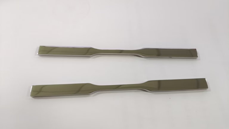
Five decisions, not five slogans
Each rule below covers one build decision: prototype first, split additive from subtractive, design for the process, merge parts, and finish what you print. Numbers come from our own shop floor.
Scout First: Print the Prototype Before You Cut Metal
The worst opening move in the film is walking into the jungle with no survey. In manufacturing the same mistake looks like buying hard tooling or cutting a full set of metal parts before anyone has held the geometry in their hands. An SLA or SLS prototype is cheap reconnaissance. In two or three days it shows screw bosses that collide with a PCB standoff, walls too thin to tap, and mating faces that never touch.
The cost gap is the point. A small SLA or SLS prototype is a fraction of a machined metal one-off, so you can afford several print rounds. We run SLA and SLS machines daily for exactly this and usually turn prototypes around in 1–3 days. Two or three iterations before the first metal cut removes most downstream design rework, and rework is where budgets die.
Know when printing is the wrong scout. If the part carries a bearing bore, a sealing face, or a thread that must hold torque, a polymer print cannot validate it. Print the housing for fit, then machine the functional insert. One medical enclosure we ran had an internal boss intersecting a standoff, a flaw obvious in a print and expensive in aluminum.
- 1Print whenYou are checking fit, clearance, ergonomics or assembly order.
- 2Machine whenThe feature is a bore, thread, seal face or press fit.
- 3Typical prototype lead time1–3 days for SLA and SLS geometry checks.
Don't Feed the T-Rex: Split Additive and Subtractive Work
Printing every part is the T-Rex approach. It works, it looks impressive, and it eats powder. SLM consumes metal powder, needs support structures that must be cut away, and leaves a rough surface that then needs finishing. On a bracket with a large open body, that is fine. On a Ø12 mm H7 bore or a valve seat, it is a slow route to a part that still does not seal.
Hybrid means you assign each feature to the process that produces it best. Print the organic lattice, the internal channel, the hollow rib that no cutter can reach. Machine the datum faces, the bores, the threads, the seal grooves and any surface that touches another part. A 5-axis center with a Ø400 mm rotary table reaches five sides in one setup, so the machined features stay concentric to the printed body.
The rule of thumb we give engineers: if a feature has a tolerance tighter than ±0.05 mm or a surface callout under Ra 1.6 μm, plan on a cutting tool. If the feature is a shape or a void that a tool cannot reach, plan on the printer. Everything else is a cost decision, not a capability one.
- 1Print featuresInternal channels, lattices, hollow ribs, complex organic skins.
- 2Machine featuresDatums, bores, threads, seal grooves, bearing seats.
Which Feature Goes Where
Use this as a first pass. Final call depends on load, material and tolerance stack.
| Feature | Better process | Why |
|---|---|---|
| Internal cooling channel | SLM 3D printing | No cutter can reach the bend. |
| Ø12 mm H7 bore | 5-axis CNC | Print bore needs reaming anyway. |
| Seal groove, Ra 0.8 μm | CNC turning | Print surface roughness is too high. |
| Large hollow bracket body | SLM 3D printing | Saves material and weight. |
| Threaded mounting holes | CNC milling or tapping | Prints strip under torque. |
| Cosmetic outer shell | SLA or vacuum casting | Smooth surface with little work. |
Outsmart the Net: Design for Additive, Then Design for Machining
DFAM is not a license to draw anything. Every overhang you keep becomes a support structure someone has to remove, and every support scar sits on a surface that may need hand work. Keep overhangs under about 45° where you can. Orient the part so the critical face points up and away from supports. Put the support contact on a non-functional surface whenever the geometry allows.
The second half is design for machining, and it is where most print-first projects lose time. Thin walls vibrate. Sharp internal corners load a small cutter and shorten tool life. Deep pockets need a cutter diameter that can reach the floor and still clear the chips. If you add a 0.5 mm corner radius or open a pocket by 2 mm, the same part often costs less to finish.
Send the model early and we return DFM notes with the quote. Quotation and free DFM analysis come back within 12 hours, and production can start within 24 hours of approval. Catching a support problem at the quote stage is free. Catching it after the build is not.
- 1OrientationPoint critical faces up so supports land on non-critical surfaces.
- 2CornersAdd a 0.5 mm internal radius so a larger cutter can finish.
- 3WallsKeep machined walls thick enough to resist cutting forces.
Part Consolidation: Fewer Joints, Fewer Fixtures, Lower Cost
A bracket assembly of six plates, twelve bolts and two dowel pins carries cost in places people forget. Every plate needs its own setup. Every joint needs a tolerance stack. Every bolt hole needs drilling on both sides. Printing the same bracket as one body removes the fasteners, the stack and most of the fixturing.
Consolidation pays best when the joints are static and the loads are moderate. It pays less when the assembly must be serviced in the field, when two halves are made of different materials, or when a bearing housing must be replaced without scrapping the frame. In those cases, keep the joint and machine the mating faces flat and parallel.
There is a second version of consolidation that gets ignored: merge the machined features into one setup. A part that needs three sides milled can often be done on one 5-axis setup with a Ø400 mm rotary table. Fewer setups means fewer datums to chase and a tighter position tolerance across features that must line up.
- 1ConsolidateStatic joints, moderate loads, no field service.
- 2Keep separateDifferent materials, wear parts, serviceable bearings.
Post-Processing Is DNA Repair: Never Skip It
A printed metal part comes off the build plate with support stubs, a rough skin and residual stress. Skip the cleanup and you get a part that fits nothing, seals nothing and may crack when it is machined. Post-processing is not decoration. It is what turns a print into a component.
The sequence matters. Remove supports, then stress relieve if the part will be machined, then cut the datums. Datums first, because every later cut references them. Then machine the functional features. Then finish: bead blasting, tumbling, anodizing, electroless nickel, powder coating or polishing depending on the environment.
We inspect 100% before shipment, with raw material check, in-process monitoring and final inspection, and reports on request. A surface that must seal gets turned or ground to Ra 0.8–1.6 μm. A surface that only needs to look good after anodizing starts around Ra 1.6–3.2 μm. Choosing the finish at the drawing stage avoids a second trip through the shop.
- 1Order of operationsSupports, stress relief, datums, functional cuts, finish.
- 2Sealing facesMachine to Ra 0.8–1.6 μm, never leave as-printed.
- 3Cosmetic facesBead blast or tumble before anodizing for even color.
Questions Engineers Ask Before the First Build
What tolerance can I expect on a printed and then machined part?
Machined features hold ±0.005 mm on our 5-axis and turning centers. Printed features that are not cut hold a much wider band, so keep functional fits on machined surfaces.
If a bore must hold an H7 fit, plan for a machining allowance on the print and cut it after.
How many prototype rounds should I plan before cutting metal?
Two or three rounds covers most fit and assembly problems. Each round takes 1–3 days for SLA or SLS geometry checks.
If the design is stable and only cosmetic changes remain, go straight to the machined version.
Can you machine a part that was printed somewhere else?
Yes, if the part has enough stock on the functional faces and a clear datum reference. We machine printed bodies regularly.
Send the model and the print parameters, and we will tell you what can be cut and what needs a redesign.
Which materials do you keep in stock for printed and machined work?
Machining covers 6061, 7075, 304, 316L, 17-4PH, 4140, TC4, Inconel, brass and engineering plastics including POM, PEEK and PC.
Printed metal work uses SLM powder, with SLA and SLS for polymer prototypes. Ask for the grade you need at quote time.
What is the minimum order quantity?
There is no minimum. We run from a single prototype to 10,000+ part runs.
Quantity mainly changes setup amortization, not whether the job is possible.
How do you handle confidentiality on new designs?
Uploads are secure and confidential, and we sign an NDA on request before files are shared.
If your program needs it, ask for the NDA first and send the model after it is signed.
Send the Model, Get a Process Plan
Upload a STEP file and we return a quote with DFM notes, a print-or-machine recommendation, and a realistic lead time. Quotation and free DFM analysis within 12 hours.
12-hour quote100% inspectionNo minimum orderNDA on request









