
7 3D Printing Inspiration Ideas to Boost Your Creativity
A working list for engineers and product designers who already know what a printer can do and want to know what it cannot finish. Each idea names the geometry, the material, and the machining step that makes it usable. Read it and you can judge which of the seven fits your next part.
Where additive stops and machining begins
The seven ideas below share one pattern: the printer builds the shape, the machining center builds the interface.
Lattice Structures for Lightweighting and Heat Dissipation
A lattice earns its place when a solid block is mostly carrying nothing. Aerospace brackets, robot arm segments, and EV battery housings are the usual candidates. Replace the core with a periodic or stochastic lattice and you drop mass fast, but you also inherit a problem: a lattice has no flat face to bolt to.
So the print becomes the inner skeleton and the machining center handles the outer contract. We face mounting bosses, bore alignment holes, and thread them on a five-axis setup. Compound angles and side features that a three-axis machine cannot reach are routine here.
Titanium and aluminum alloys are the common choices. We machine lattice components in TC4 (Ti-6Al-4V), 6061-T6, and 7075, holding ±0.005 mm on critical interfaces and Ra 0.8–1.6 μm on sealing faces. The printed core stays light; the machined faces stay true.
- 1Good fitBrackets, arm links, housings where stiffness matters more than mass
- 2Poor fitParts under 20 mm with no room for tool clearance after printing
Functionally Graded Molds for Injection Molding
A mold insert does not need one material throughout. Print a cavity core in hard tool steel where the plastic flows and abrades, then transition to a tougher, more ductile steel near the edges so the insert absorbs shock during ejection. The gradient is a printing decision, not a welding one.
What follows is machining. A printed insert arrives with a rough surface and no reliable datum. We skim the parting line, grind the cavity to the target finish, and cut the ejector pin holes and water line ports to size. Without that step the insert will flash and the cycle will drift.
This idea suits low to mid-volume tooling and bridge tools used before a hardened production mold is ready. It does not suit a 500,000-shot program where a forged block still wins on cost per part.
- 1Good fitBridge tooling, low-volume inserts, fast design iterations
- 2Poor fitHigh-shot-count production molds with tight cycle targets
Patient-Specific Surgical Guides and Implants
Anatomy is not symmetric and not flat. A guide that fits one patient's bone contour will not fit the next. Printing turns that constraint into an advantage: scan, model, print a guide that sits on the actual surface, then machine the mating features that interface with the drill or the implant system.
The machining side is where tolerance lives. Bone-contact surfaces can stay as printed, but drill bushings, screw holes, and implant connections need real numbers. We hold ±0.005 mm on those features and work to ISO 13485:2016 process controls. Titanium grades TA1, TA2, and TC4 cover most implant-adjacent work.
Do not print a load-bearing implant and call it done. Fatigue performance of as-printed metal depends on build orientation and internal defects. Machining the critical surfaces removes the layer texture where cracks start.
- 1Good fitCutting guides, drill templates, trial implants, fixtures
- 2Poor fitLong-term load-bearing implants without full post-processing
Custom End-Effectors and Grippers for Collaborative Robots
A cobot gripper is usually a one-off. The part it picks has a shape nobody sells a jaw for, and the payload is low enough that weight matters. Printing the body lets you put material only where the load path runs and leave the rest open for cable routing.
Then the interfaces get machined. Mounting flanges, dowel pin holes, and the tool-side bolt pattern must match the robot wrist exactly or the gripper will not repeat. We cut those on the five-axis center, along with any vacuum port or sensor pocket.
Printed plastic bodies work for light duty. For higher grip force or repeated cycles, print the frame in aluminum and machine the jaw surfaces, then anodize. The printed aluminum gives the shape; the machined faces give the wear resistance.
- 1Good fitOne-off grippers, vacuum cups, sensor brackets, cable guides
- 2Poor fitHigh-cycle production grippers where a billet body is cheaper per unit
Conformal Cooling Channels in Die-Casting and Injection Molds
Straight drilled water lines can only cool what a drill can reach. A conformal channel follows the cavity surface at a constant distance, which shortens cycle time and reduces warpage in thick sections. This is one of the strongest 3D printing inspiration ideas for tooling, and it has a hard limit: the channel must not leak.
Leak-tightness is a machining and inspection problem. We machine the insert seats, cut the thread ports, and pressure-test before the insert goes into the mold base. The printed channel itself is rarely the failure point. The joint between the printed insert and the drilled manifold usually is.
Design the interface with a real seal in mind. An O-ring groove or a tapered thread is easier to machine than to print. Keep the printed-to-machined transition on a flat face you can reach with a tool.
- 1Good fitThick-wall parts, hot spots, cycle-time-driven programs
- 2Poor fitSimple flat parts where drilled lines already cool evenly
Which hybrid route fits which part
Use this as a first filter before you send a model.
| Idea | Printer builds | Machining center does | Typical material |
|---|---|---|---|
| Lattice structure | Inner skeleton | Bosses, bores, threads | Ti-6Al-4V, 6061-T6 |
| Graded mold insert | Cavity gradient | Parting line, ports | Tool steel |
| Surgical guide | Bone-contact surface | Bushings, screw holes | TA2, TC4 |
| Cobot end-effector | Body and load path | Wrist flange, jaw faces | Aluminum, POM |
| Conformal cooling | Curved channels | Seats, ports, seal faces | Tool steel, copper |
| Hybrid spare part | Near-net blank | All critical features | Aluminum, stainless |
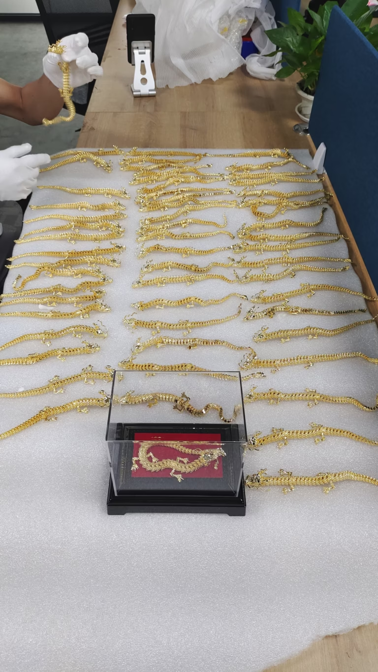
| Sculptural part | Freeform skin | Mounting and drive features | Aluminum, brass |
Hybrid Spare Parts: From Digital Inventory to Physical Product
Legacy machines break and the drawing is gone. You have the broken part in hand and a print file is faster to make than a new casting pattern. Print a near-net blank, then machine the features that have to mate with the rest of the machine.
The economics work when the part is complex, the quantity is one, and the downtime cost is high. They do not work when a standard bar stock part can be turned in an afternoon. Be honest about which case you are in.
For reverse-engineered parts, measure first. We check the worn part, build a model, print a blank, then machine and inspect against the measured fits. Reports are available on request, and 100% inspection happens before shipment.
- 1Good fitObsolete castings, discontinued brackets, low-quantity legacy parts
- 2Poor fitSimple shafts and plates available as stock material
Art-to-Engineering: Complex Sculptural Components with Mechanical Function
Some parts have to look like something and still do a job. Architectural hardware, consumer product shells, and exhibition mechanisms fall here. The printed skin carries the form; the machined inserts carry the function.
Split the model early. Decide which surfaces are cosmetic and which are functional, then put the split line where a tool can reach it. A brass or aluminum sculptural part can be printed close to shape and finished by machining the pivot holes, bearing seats, and mounting threads.
Finishing matters as much as geometry on these parts. Anodizing, polishing, and bead blasting change how the part reads. Laser marking works down to 1.5 mm character height if you need a logo or a serial number.
- 1Good fitHardware, enclosures, display mechanisms, one-off fixtures
- 2Poor fitParts where the cosmetic surface is also a sealing or bearing surface
Questions engineers ask before going hybrid
When is a hybrid print-plus-machine part cheaper than machining from solid?
It usually wins when the geometry is internal or organic and the material is expensive. A lattice core or a conformal channel removes a lot of stock that a cutter would otherwise have to clear, and that cutting time is what you are buying back.
It usually loses when the part is prismatic. A simple bracket with flat faces and through holes is faster on a three-axis mill than in any print-then-machine loop.
How do you hold a printed blank for the second operation?
We design the fixturing into the process, not the part. Printed blanks get a machining allowance on the faces we will clamp, and we often print a temporary tab or boss that gets cut away after the critical features are done.
For thin lattice sections we use soft jaws or a sacrificial fixture machined to the blank contour. Clamping pressure is set low enough that the lattice does not crush.
What tolerance can you hold on a printed-and-machined part?
On machined features, ±0.005 mm on critical dimensions. As-printed surfaces are far looser and should never be a datum.
Any hole that carries a bolt, a pin, or a bearing gets machined. Surfaces that only carry airflow or appearance can stay as printed.
Which materials do you machine after printing?
Aluminum 6061-T6, 7075, and 2024; stainless 17-4PH and 316L; titanium TA2 and TC4; copper and brass for thermal and cosmetic work. Tool steel is common for mold inserts.
On the plastic side we machine POM, PEEK, ABS, and PC when the printed body needs threaded inserts or tight bores.
Can you inspect and document the machined features?
Yes. Inspection covers raw material check, in-process monitoring, and final inspection, with 100% inspection before shipment. Reports are available on request.
If your program needs traceability, say so at quote time so the inspection plan is written into the job rather than added later.
How fast can a hybrid job start?
Quotation and free DFM analysis come back within 12 hours. Production can start within 24 hours of approval, and parts ship in 3–5 days.
No minimum order quantity applies. One prototype and a 10,000-part run go through the same process.
Send the model. We will tell you where to split it.
Upload your part and get a quotation with free DFM analysis within 12 hours. Uploads are secure and confidential, and an NDA is available on request.
12-hour quote±0.005 mm100% inspectionNo MOQ









