
5 Essential CNC 3008 Secrets to Boost Your Machining Precision
A CNC 3008 is a light benchtop router. Its accuracy limits come from the frame, the motion train and the fixture, not from the controller. This guide explains the five changes that boost your machining precision, and when each one stops paying off.
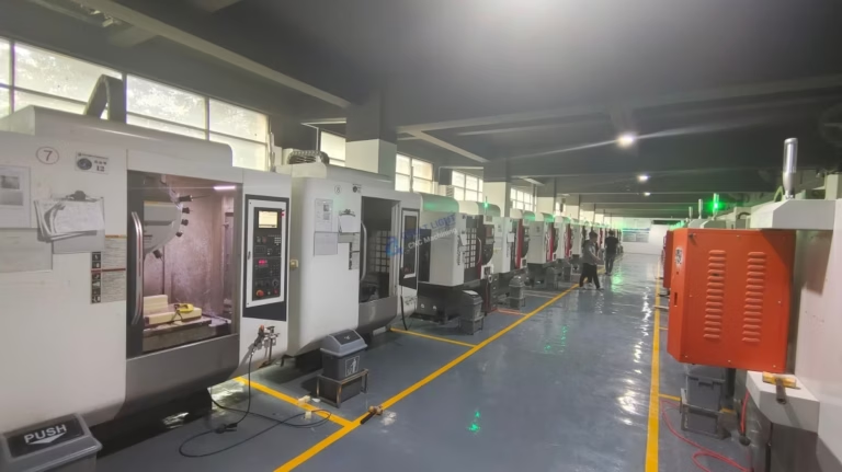
Frame stiffness sets the floor on how to boost your machining precision
An aluminium extrusion gantry behaves like a spring. Push a 6 mm end mill through 6061 at 0.4 mm depth of cut and the reaction load deflects the gantry by tens of microns before the cut stabilises. That deflection shows up as taper on side walls, chatter marks on floors, and a surface finish that moves around between parts.
The fix is not a stiffer controller. It is mechanical. Bolt the base to a rigid steel or granite plate, then re-check gantry squareness with a granite square and a 0.01 mm dial indicator. A 0.05° twist tilts the tool through the cut and produces tapered pockets. Reaming the dowel-pin holes and lapping the mounting faces brings alignment back to roughly 0.01 mm across the work envelope.
Cross-bracing the uprights matters more than adding mass. Two diagonal braces on the rear of the gantry raise the first natural frequency enough to move chatter out of the normal spindle band. On a 3008-class frame, spindle speeds between 8,000 and 12,000 rpm are the worst region for resonance.
Know the boundary. If your part needs ±0.005 mm over a 300 mm length, no amount of bolting will get a light extrusion frame there. That tolerance belongs to a cast-iron or polymer-concrete machine. Stiffening a benchtop router buys you repeatability and finish, not sub-10-micron geometry.
- 1Check squareness firstGranite square plus dial indicator before any other tuning.
- 2Brace before adding massDiagonal rear braces shift the resonance band faster than weight.
- 3Accept the limitLight frames hold finish and repeatability, not ±0.005 mm geometry.
Backlash lives in four places, not one
Most operators chase backlash in the lead nuts and stop there. On a CNC 3008 the lost motion usually sits in four places at once: the anti-backlash nut, the motor coupling, the spindle collet, and the belt or coupler between motor and screw. Fixing one leaves the other three to show up as oval holes and reversed-tool-path marks.
Measure before you adjust. Mount a dial indicator on the table, touch the indicator tip against the spindle nose, and jog the axis 0.10 mm forward and back ten times. Read the difference between commanded and actual travel. Anything above 0.03 mm on a benchtop machine will show in the part.
Replace the stock collet nut with a ball-bearing nut that clamps uniformly. A standard nut pulls the collet slightly off-axis as it tightens, and that tilt becomes runout at the tool tip. A precision nut costs little and removes one error source entirely.
Software backlash compensation is a patch, not a cure. It corrects position at reversal but does nothing for the elastic wind-up that happens during the cut. Use it after the mechanics are tight, and keep the compensation value under 0.02 mm. Larger values hide a mechanical fault that will move as the machine warms.
- 1Four sourcesNut, coupling, collet, and belt or coupler.
- 2Measure with an indicatorCompare commanded travel against actual over ten reversals.
- 3Cap compensationKeep software values small; fix the mechanics instead.
Feeds, speeds and chip thinning change the load
Chip thinning is the reason a light machine can cut aluminium well and steel badly. When the radial engagement drops below half the cutter diameter, the actual chip gets thinner than the feed per tooth suggests. The cutting edge rubs instead of shearing, and the load goes up, not down.
The correction is simple arithmetic. For a 50 percent radial engagement, multiply your feed per tooth by 1.0. At 25 percent engagement, multiply by about 1.4. At 10 percent, multiply by roughly 2.5. This keeps the chip thick enough to shear cleanly and pulls heat out of the cut with the chip.
On a 3008 frame, start conservative. A 6 mm three-flute carbide end mill in 6061 runs well near 10,000 rpm, 0.05 mm per tooth feed, and 0.5 mm axial depth. Surface speed around 190 m/min keeps the tool cool without loading the spindle above 60 percent of its rated power.
Steel is a different job. At 4140 or 1045, drop surface speed to 90–120 m/min, use four flutes, and keep the radial engagement at 40–50 percent. The frame will deflect less because the tangential force is lower, even though the material is harder.
- 1Thin-chip correctionRaise feed per tooth as radial engagement drops.
- 2Aluminium baseline6 mm three-flute, 10,000 rpm, 0.05 mm per tooth.
- 3Steel baselineFour flutes, 90–120 m/min, 40–50 percent radial.
Workholding is where precision is lost
A rigid machine with a soft fixture cuts like a soft machine. The workpiece moves under load, the tool marks the part, and the final dimension drifts from the programmed value. On a benchtop router the fixture is often the weakest element in the loop.
Support the part close to the cut. Every millimetre of unsupported overhang amplifies deflection. For thin plates, back the work with a sacrificial plate and clamp within 20 mm of the cutting edge. For tall parts, add a mid-height support rather than relying on the vise jaws alone.
Zero-point systems pay off on repeat work. A pallet with dowel pins and a repeatable stop lets you remove a part, measure it, and put it back within a few microns. That turns a two-setup job into a one-setup job and removes a whole class of datum errors.
Check the vise itself. A worn vise jaw lifts the part as it clamps, so the top face is no longer parallel to the table. Indicate the jaw face and the part top after clamping. If the top moves more than 0.02 mm, the vise is the problem, not the machine.
- 1Clamp near the cutKeep unsupported overhang under 20 mm where possible.
- 2Zero-point palletsRepeatable stops remove datum errors between setups.
- 3Indicate after clampingA worn vise lifts the part and breaks parallelism.
Thermal drift and metrology close the loop
A CNC 3008 warms up during the first hour of cutting. Ballscrews grow, the spindle housing expands, and the gantry changes shape by a few microns. On a short part this is noise. On a long part measured against a cold datum, it becomes a real dimensional shift.
Warm the machine before the first finish pass. Run a 20-minute warm-up cycle at your normal cutting speed and load. Then set your work offset. If the shop temperature swings more than 3 °C across a shift, re-check the offset after lunch rather than trusting the morning value.
Measure with the right tool. A 0.01 mm dial indicator is sufficient for setup, but for final inspection use a micrometer or a coordinate measuring machine with a stated uncertainty below one third of your tolerance. If your tolerance is ±0.05 mm, the inspection tool should be good to ±0.015 mm.
Record what you measure. A simple log of offset, temperature and part size over a week shows whether the drift is thermal or mechanical. Thermal drift reverses when the shop cools. Mechanical wear does not.
- 1Warm up before offsetRun 20 minutes at cutting speed and load.
- 2Rule of thirdsInspection uncertainty should be below one third of tolerance.
- 3Keep a logThermal drift reverses; wear does not.
Which secret to apply first
Match the symptom to the mechanical fix and the expected gain. Gains are typical for a well-tuned benchtop machine, not guaranteed values.
| Symptom | First fix | Typical gain |
|---|---|---|
| Tapered walls on deep pockets | Square and brace the gantry | Taper reduced, finish steadier |
| Oval holes on reversal | Tighten nut, coupling, collet | Lost motion under 0.03 mm |
| Chatter at 8,000–12,000 rpm | Add rear diagonal bracing | Chatter band moves up |
| Rubbing, poor chip evacuation | Apply chip-thinning feed | Cleaner shear, cooler tool |
| Dimensions drift over a shift | Warm up, re-set offset | Drift mostly removed |
| Part moves during clamping | Support within 20 mm of cut | Datum errors drop |
| Repeat setup takes two hours | Add zero-point pallet | Setup cut to minutes |
When to tune the machine and when to change it
If your tolerance is ±0.05 mm or looser, tune the frame, motion train and fixture — that is enough. If you need ±0.005 mm over a long part, stop tuning the benchtop and move the job to a machine built for it.
Questions engineers ask next
How much backlash is acceptable on a benchtop CNC?
Aim for under 0.03 mm of lost motion measured at the spindle nose with a dial indicator. Above that, oval holes and reversal marks appear even on aluminium.
If you cannot get below 0.05 mm after tightening the nut, coupling and collet, the screw or the belt is worn and should be replaced.
Does chip thinning apply to finishing passes?
Yes, and it matters most there. A light finishing pass at low radial engagement rubs unless the feed per tooth is raised to compensate.
For a 10 percent radial engagement, multiply the feed per tooth by roughly 2.5 so the chip still shears rather than burnishing.
How long should a CNC 3008 warm up before a finish cut?
Twenty minutes at normal cutting speed and load is a practical figure for a benchtop machine. Shorter warm-ups leave the ballscrew and spindle housing still growing.
Set the work offset after the warm-up, not before. Setting it cold is the most common cause of a first-part dimension error.
Can software compensation replace mechanical fixes?
No. Compensation corrects commanded position at reversal, but it cannot correct elastic wind-up during the cut.
Use it only after the mechanics are tight, and keep the value under 0.02 mm. A large compensation value hides a fault that will move as the machine warms.
What inspection uncertainty do I need for a ±0.05 mm part?
Use the rule of thirds. The measuring tool should be at least three times better than the tolerance, so ±0.015 mm or finer.
A 0.01 mm dial indicator is fine for setup but not for final acceptance. Use a micrometer or a CMM with a stated uncertainty.
When should a benchtop job move to a production shop?
When the tolerance tightens below ±0.02 mm, when the part needs simultaneous multi-face work, or when the run count climbs past a few dozen pieces.
At that point the setup time and scrap rate on a light machine outweigh the savings. Production machines hold ±0.005 mm and inspect 100 percent before shipment.
Send us the part that outgrew the benchtop
Upload a drawing and we return a quotation with a free DFM analysis within 12 hours. No minimum order quantity, from one prototype to 10,000+ parts.
12-hour quote100% inspectionNDA on request
More machining notes
We publish setup notes, tooling trials and inspection data from the factory floor.











