
7 Common Casting CNC Machining Mistakes That Cost You Time and Money
This page is for design engineers and sourcing teams who machine castings into finished parts. It lists seven mistakes we see on real RFQs, explains why each one costs money, and shows what to check before the first cut.
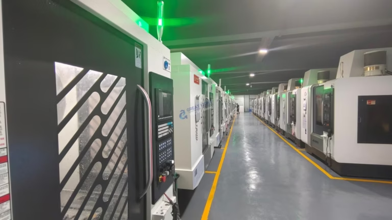
Where casting tolerances end and machining tolerances begin
A casting is a rough blank with its own dimensional spread, skin, and internal stress. Machining it well means working with those facts, not against them.
Blanket tolerances tighter than the process can hold
The most expensive line on a drawing is often a tolerance nobody needs. A ±0.005 mm callout on every face forces extra finishing passes on surfaces that only need to clear a weld or sit against a gasket. Machining time climbs, tool life drops, and scrap rate follows.
Tolerance bands drive cost non-linearly. Going from ±0.05 mm to ±0.01 mm might add one light pass. Going from ±0.01 mm to ±0.005 mm can force a temperature-stable setup and a second machine. On a 10,000-part run, that difference is real money.
Tighten only what the fit, seal, or bearing interface requires. Mark the datum surfaces, leave cosmetic faces open, and let the shop choose the strategy. If a callout exists because a previous supplier missed it, say so on the RFQ. That context changes how we plan the setup.
- 1Ask what the tolerance protectsIf no answer exists, loosen it.
- 2Group tight featuresKeep them reachable in one setup where possible.
Treating a raw casting like a uniform billet
A casting is not a block of 6061. It has a cast skin, a variable as-cast surface, and internal stress from cooling. The first cut removes support and releases that stress. If the part is measured right off the machine and packed the same day, it can still move overnight.
The fix starts upstream. Castings should be stress-relieved before finish machining, and the first operation should establish a stable datum rather than clamp on a rough, angled surface. On thin-wall castings, take balanced cuts on both sides instead of removing everything from one face.
We see this most on aluminium housings and ductile iron brackets. Both machine cleanly, both distort if the sequence is wrong. When a casting is the blank, tell us the alloy, the casting process, and whether it was heat-treated. Those three facts shape the whole plan.
- 1Stress relief before finishingEspecially on thin-wall and long parts.
- 2Balance material removalAlternate faces to limit bowing.
- 3Rest before final inspectionLet the part settle, then measure.
Fixturing planned around the CAD model, not the casting
A fixture that clamps on a machined surface is simple. A fixture that clamps on a cast surface is not. As-cast faces vary part to part, so a hard stop that works on one blank may not seat on the next. The result is a setup that shifts mid-run.
Good casting fixtures use the machined datum from operation one, or they use a self-centering or conforming contact that tolerates the cast spread. For thin-wall parts, support underneath the cut zone, not across it. Clamping pressure should be low and repeatable.
If your drawing allows a small boss or pad for clamping, add it and remove it in the last operation. That single feature often removes a custom fixture and a day of setup. It also makes the part easier to quote, because the shop can plan around a known contact point.
Splitting one casting across several suppliers
Sending the casting to one shop, the machining to a second, and the finish to a third looks like it saves money on paper. In practice it adds handling, shipping, and a quality argument nobody can settle. When a bore is out of position, both shops point at the other.
The tolerance stack across suppliers is the hidden cost. Each move adds a re-datum and a new inspection. On a casting with a ±0.1 mm as-cast spread, that stack can eat the entire machining allowance before a tool touches the part.
One supplier holding the casting, machining, and inspection removes the argument. We keep casting and CNC in the same workflow, so the datum used for the first cut is the datum used at final inspection. If a separate foundry is required, agree on who owns the first-article report.
When casting plus CNC is the right route, and when it is not
Use this as a first filter before you commit a casting to a machining plan.
| Part condition | Casting + CNC fit | What to watch |
|---|---|---|
| Complex internal passages | Strong fit | Machining access to sealing faces |
| Simple prismatic block, low volume | Poor fit | Machined-from-solid is faster |
| Thin walls under 3 mm | Possible, needs care | Distortion after stress relief |
| Sealing or bearing bores | Strong fit | Tight tolerance only on those bores |
| Cosmetic visible surfaces | Strong fit | Cast skin defects show after anodizing |
| Prototype under 20 pieces | Often poor fit | Tooling cost per part stays high |
Surface finish specified by habit, not by function
Ra 0.8–1.6 μm is a sensible default for many sealing and sliding surfaces. It is a waste on a bracket face. The reverse is also true: a Ra 3.2 μm callout on a hydraulic seal land will leak, no matter how well the dimensions are held.
Finish and tolerance interact. A tighter finish usually requires a lighter finishing pass, which can change the effective size if the tool wears. On cast iron, the cast skin also matters, because graphite and porosity at the surface behave differently from the machined core.
Call out finish only on the faces that touch, seal, slide, or are visible. For everything else, let the shop use a general note. That keeps cycle time down and gives the finishing department a clear list of what actually needs attention.
- 1Sealing facesRa 0.8–1.6 μm or finer as required.
- 2Bearing boresMatch the bearing maker's spec, not a habit.
- 3Cosmetic facesFinish matters more than tolerance here.
Planning the job around one machine type
A casting often needs a mill for the faces, a lathe for a bore, and a drill for a bolt circle. If the plan assumes all of that happens on one machine, the shop either compromises the setup or moves the part and re-datums it. Both cost accuracy.
The better approach is to decide which features must stay in one setup and which can move. A bearing bore and its mounting face belong together. A bolt circle on the opposite side usually does not, as long as the datum is transferred cleanly.
Mill-turn centers handle this well for round-and-prismatic parts, since turning and milling share one spindle. For large frames, a 5-axis machine with a Ø400 mm rotary table can reach five faces without a second fixture. The point is to choose the setup by feature relationship, not by machine count.
No material certification or traceability on the casting
A machined part is only as good as the metal it came from. Castings can vary in chemistry, hardness, and porosity from lot to lot, and the difference often shows up after machining, not before. Without a heat number and a material certificate, there is no way to trace a failure back.
For regulated work in medical, automotive, and aerospace, traceability is not optional. Ask for the mill or foundry certificate, the heat number, and any heat-treatment record. Keep the casting lot tied to the finished part lot, so a problem can be contained to one batch.
We check incoming material and keep records for every run. Inspection reports are available on request, and 100% inspection happens before shipment. For defense or medical programs, an NDA can be signed before drawings are shared.
- 1Ask for the heat numberMatch it to the mill or foundry certificate.
- 2Record heat treatmentTime, temperature, and the lot it covered.
- 3Tie lots togetherCasting lot to finished part lot.
Common questions about casting CNC machining
How much machining allowance should a casting have?
It depends on the as-cast spread and the part size. Small aluminium castings often need 0.5–1.0 mm per face. Larger iron or steel castings may need 2–3 mm to clean up after distortion.
Send the casting drawing with the as-cast tolerance and we will confirm the allowance before quoting.
Can you machine a casting that was made by another foundry?
Yes. We need the casting drawing, the alloy, the as-cast tolerance, and whether it was stress-relieved. A first-article inspection on the incoming blanks helps us set the datum.
If the castings vary too much, we will say so before cutting rather than chase the tolerance all run.
Do you stress-relieve castings before machining?
We do when the geometry or alloy calls for it, particularly on thin-wall or long parts where distortion after machining is likely. The method depends on the material.
For aluminium we typically rough machine, relieve, then finish. On iron castings the relief step usually happens before the first cut.
What tolerance can you hold on a machined casting?
We hold ±0.005 mm on critical machined features when the setup and material allow it. As-cast surfaces keep their own wider tolerance.
Tell us which features carry the tolerance. Holding everything to ±0.005 mm adds cost without adding function.
How do you handle confidential casting drawings?
Uploads are secure and confidential. We can sign an NDA before drawings are shared, and we only use the files for the quoted work.
If your program requires it, we can restrict who inside the shop sees the model and the process sheets.
Send the casting drawing before you commit to a machining plan
We review the casting, the datum, and the tolerance stack, then send a quote with DFM feedback within 12 hours.
12-hour quote100% inspection±0.005 mm toleranceNDA on request









