
A CNC Milling Machine 2: How It Works and When to Use It
This page explains what a cnc milling machine 2 configuration is, how the cutting cycle runs from CAD to finished part, and which parts belong on a mill. Written for design engineers and sourcing staff who need to pick a process and read a quote with confidence.
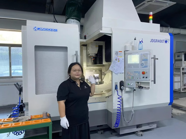
Milling as a subtractive process
A mill removes material with a rotating cutter. Everything else on this page follows from that one fact.
How a CNC milling machine works
A CNC milling machine holds a workpiece on a table or fixture and drives a spinning cutter into it along programmed paths. The cutter is a multi-tooth tool: each flute takes a small chip per revolution. Feed rate, spindle speed, and depth of cut together set the chip load, and the chip load is what decides whether the tool cuts cleanly or rubs and burns.
CNC stands for computer numerical control. The machine does not read a 3D model directly. CAM software converts the model into toolpaths, then posts G-code: coordinates, feed rates, spindle commands, tool changes. The controller executes that code, so the same program produces the same geometry on every cycle. Repeatability comes from the code and the machine's rigidity, not from operator feel.
The cutting sequence usually runs roughing first, then semi-finishing, then finishing. Roughing removes bulk material with a large tool and generous stepover. Finishing uses a smaller tool, tighter stepover, and higher spindle speed to hit the drawing's surface callout. On a part with several faces, each face may need its own setup unless the machine has enough axes to reach it in one pass.
- 1Climb millingCutter rotation moves with the feed. Better finish and longer tool life on rigid setups.
- 2Conventional millingOpposite direction. Useful on older machines with backlash, rarely needed today.
- 3Chip evacuationDeep pockets need air blast or through-spindle coolant, or chips get recut.
Key components and what each one controls
The spindle is the heart of the machine. Its taper, maximum rpm, and torque curve set what tools you can run and how fast you can run them. A high-speed spindle with 20,000 rpm suits small cutters in aluminium. A geared spindle with high torque at low rpm suits steel and titanium. Neither is universally better.
Linear axes position the part relative to the tool. Ball screws and linear guides convert motor rotation into travel. The published travel envelope tells you the largest single part the machine can reach: 4,000 × 400 × 150 mm on our largest mill, down to 500 × 310 × 200 mm on the compact machines. A part that fits the envelope can still fail if the fixture pushes it outside the reachable volume.
The tool changer matters more than buyers expect. A 24-pocket magazine lets a job run unattended for hours. It also reduces the number of times an operator has to stop the spindle. On short prototype runs this matters less, so do not pay for a large magazine if the part needs three tools.
3-axis, 4-axis, and 5-axis: how to choose
A 3-axis mill moves X, Y, and Z. The tool always points down. It handles plates, brackets, housings, and any part where all machined faces can be reached from a few directions. It is the cheapest option per part and the easiest to inspect, because every feature is set up in a known orientation.
A 4-axis mill adds rotation around one axis, usually A. That lets the machine index to a new face without a human re-fixturing the part. Shafts, cylinders, and parts with features on four sides are the natural fit. The rotary table on our 4-axis machines is Ø400 mm, which sets a practical size limit for what can be indexed.
A 5-axis mill adds a second rotary axis, so the tool can approach the part from almost any angle in a single setup. Impellers, turbine blades, deep cavities with drafted walls, and parts with compound angles are the reason this exists. The trade-off is real: 5-axis programming takes longer, simulation is mandatory, and the machine is more expensive per hour. Do not specify 5-axis for a part that a 3-axis machine can reach with two setups.
- 1Use 3-axis whenFaces are orthogonal and reachable from limited directions.
- 2Use 4-axis whenFeatures repeat around a single axis of rotation.
- 3Use 5-axis whenUndercuts, compound angles, or one-setup accuracy dominate.
Axis count at a glance
Pick the lowest axis count that reaches every feature. More axes cost more per hour.
| Configuration | What moves | Typical parts | Watch out for |
|---|---|---|---|
| 3-axis | X, Y, Z only | Plates, brackets, housings | Multiple setups on complex parts |
| 4-axis | X, Y, Z plus one rotary | Shafts, cylinders, four-sided parts | Rotary table size limits part diameter |
| 5-axis | X, Y, Z plus two rotary | Impellers, blades, deep cavities | Higher programming and hourly cost |
| Mill-turn | Turning plus milling in one | Bushings, fittings, motor housings | Not ideal for large prismatic parts |
Materials, tolerances, and surface finish
Aluminium is the default for milled prototypes. Grades 6061 and 7075 cut fast, hold tight tolerances, and take anodizing well. Stainless 303 and 304 machine cleanly but work-harden if the cutter dwells. Titanium TC4 and Inconel need low surface speed, rigid tooling, and patience; they are the materials where a shop's experience shows up in the invoice.
Tolerance is a cost driver, not a checkbox. A general tolerance of ±0.1 mm is routine. Tightening to ±0.005 mm changes tool selection, inspection time, and sometimes the machine. Ask for the tightest tolerance only on the features that need it, and leave the rest at a general callout. That single decision often removes a finishing pass.
- 1Ra 0.2–0.8 μmFine finish, usually needs a finishing pass with a small stepover.
- 2Ra 0.8–1.6 μmStandard machined finish for most functional parts.
- 3Ra 1.6–3.2 μmAs-machined. Fine for hidden faces and non-sealing surfaces.
Where milled parts are used
Aerospace brackets, housings, and structural fittings are milled from aluminium and titanium because the process holds thin walls and tight hole positions. Automotive and EV work uses milling for motor mounts, battery tray components, and prototype engine parts before a casting or forging is cut. Medical devices rely on it for instrument bodies and implant tooling in stainless and titanium.
Robotics is a growing share of the work. Joint housings, actuator bodies, and custom end-effector plates all need pockets, bores, and bolt patterns that must line up on assembly. Milling gives that alignment in one setup on a 4-axis or 5-axis machine. Electronics and industrial machinery follow the same logic at smaller scale: heat sinks, chassis plates, and fixture plates.
Milling is not always the answer. A thin sheet panel belongs on a laser or punch. A hollow, thin-walled shell in high volume belongs in die casting or injection molding. A part with no flat fixturing surface and no way to hold it is a problem for any mill. When the geometry fights the process, we say so.
How to prepare a part for quoting
Send a STEP file plus a 2D drawing that carries tolerances, material, finish, and any critical features. If a dimension is not on the drawing, it will be machined to a general tolerance. If a finish is not specified, it will be left as-machined. Both are fine, as long as you know that is what you asked for.
We return a quotation and a free DFM review within 12 hours. That review flags features that are hard to reach, walls that may deflect, and tolerances that will drive cost. Production can start within 24 hours of approval, and parts ship in 3–5 days. There is no minimum order quantity: one prototype and a 10,000-part run both go through the same process.
We run 127 high-precision CNC machines across three wholly-owned plants covering 7,600 m², with 16 simultaneous 5-axis machining centers and 12 four-axis mills. Every part is inspected before shipment, and reports are available on request. Uploads stay confidential and an NDA is available if your program requires one.
- 1SendSTEP file, 2D drawing, material, finish, target quantity.
- 2Get backQuote plus DFM notes within 12 hours.
- 3ThenProduction starts within 24 hours of approval.
Common questions from engineers
What is the difference between a machining center and a milling machine?
They overlap heavily. A milling machine usually means a machine with a rotating cutter and a movable table. A machining center adds an automatic tool changer and an enclosed work envelope, so it can run a sequence of tools without an operator.
In a job shop the terms are used loosely. What matters for quoting is axis count, spindle speed, and travel size, not the label.
When should I specify 5-axis instead of 3-axis?
Specify 5-axis when the part has undercuts, compound angles, or features that cannot be reached from a few orthogonal directions. It also helps when re-fixturing would stack up error on a tight position callout.
If a 3-axis machine can reach every feature in two or three setups, use it. The hourly rate is lower and inspection is simpler.
What tolerance can milling actually hold?
We work to ±0.005 mm on features that need it. That is not a blanket tolerance across the whole part. It applies to the specific dimensions called out on the drawing.
General tolerances of ±0.1 mm are routine and cost far less. Keep the tight callouts on the features that function and relax the rest.
Which materials are available for milled parts?
Aluminium including 6061, 7075, 2024, and 5083; stainless 303, 304, 316L, 17-4PH, and 440C; steels such as 1018, 1045, 4130, and 4140; copper and brass grades; titanium TC4 and TA2; Inconel; magnesium; and engineering plastics including POM, PEEK, and PC.
Material choice drives tooling, speed, and finish. Tell us the function and the environment, and we can suggest an alternative if one is easier to machine.
Can you machine a single prototype without a minimum order?
Yes. There is no minimum order quantity. We run from one prototype to 10,000+ part runs on the same equipment and process.
For prototypes we recommend the DFM review first, because a small geometry change can remove a whole machining operation and cut cost before the first chip is cut.
How is my design kept confidential?
Uploads are secure and confidential. We do not share customer files or part geometry. An NDA is available on request if your program requires a signed agreement before files are sent.
If you need to limit what we see, send a simplified model with the critical features and tolerances marked, and we can quote from that.
Send a drawing, get a milling quote
Upload your STEP file and 2D drawing. We return a quotation and a free DFM review within 12 hours, and production can start within 24 hours of approval.
12-hour quoteNo MOQ100% inspectionNDA on request









