
Accurate CNC Master Accuracy
This page is for engineers and buyers who need to know how tight a machined part can actually be held, and what drives the cost of that accuracy. It covers machine geometry, thermal drift, workholding, in-process probing, and the cases where chasing a tighter number is a waste of money. By the end you can read a drawing and tell which tolerances matter and which do not.
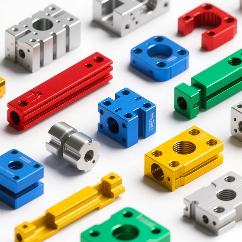
What accurate CNC master accuracy means in the shop
Accuracy is not one number. It is the sum of machine geometry, spindle behavior, fixturing, and how you measure the result.
Where the last 0.01 mm comes from
A CNC machine does not hold a tolerance because of the controller alone. Squareness between axes, ballscrew pitch error, and spindle runout set the floor before the first chip is cut. A machine that is 0.02 mm out of square cannot be program-compensated into a 0.01 mm true position. It has to be mechanically corrected first.
Thermal growth is the second limit. A spindle running at 12,000 rpm for two hours will move the tool tip 10–30 μm along Z on some machines, depending on cooling. We run warm-up cycles and let spindles stabilize before finishing passes. For parts with ±0.005 mm callouts, the roughing and finishing operations are often split across different times of day so the machine is at the same thermal state.
Workholding adds the third variable. A vise clamped at 4,000 N will distort a thin-wall aluminum housing. Soft jaws bored in place, vacuum chucks, or expanding mandrels remove that error. The fixture should be treated as part of the tolerance stack, not as an afterthought.
- 1SquarenessCheck with a granite square and dial indicator; adjust mechanically, not in the control.
- 2Thermal stateWarm up 30–60 minutes; hold the same state for roughing and finishing.
- 3WorkholdingBore soft jaws in place; match clamping force to wall thickness.
- 4Tool runoutHold under 5 μm TIR with shrink-fit or hydraulic holders for finishing.
Fewer setups, smaller error stack
Every time you move a part from one fixture to another, you add a locating error. Three-axis machining of a complex part often needs four or five setups. Each setup contributes 5–15 μm of positional variation. Five-axis machining with a trunnion or a Ø400 mm rotary table can machine five faces in one setup, so that stack collapses to a single datum.
The trade-off is that five-axis machines are not automatically more accurate. They are more accurate per setup. If the part is simple and can be done in two setups on a three-axis mill, the three-axis route is often faster and cheaper. Five-axis earns its cost when the part has compound angles, deep pockets, or features that must be true to each other from multiple directions.
We run 16 simultaneous five-axis machining centers, 12 four-axis mills, 27 three-axis machines, and 16 mill-turn centers. The mix matters because not every part belongs on a five-axis. Sending a simple turned bushing to a five-axis center wastes spindle time and money. Matching the machine to the feature is part of holding accuracy at a sane cost.
- 1Use five-axis whenCompound angles, deep cavities, or features true to multiple datums.
- 2Use three-axis whenPrismatic parts with simple features and flat datums.
- 3Use mill-turn whenCylindrical parts with cross holes or flats that need one setup.
Accuracy and finish by machine class
Numbers below are what we hold in routine production, not best-case lab results.
| Machine class | Typical tolerance | Typical finish | Best for |
|---|---|---|---|
| Three-axis mill | ±0.01 mm | Ra 1.6–3.2 μm | Prismatic parts, flat datums, simple pockets |
| Four-axis mill | ±0.01 mm | Ra 0.8–1.6 μm | Parts with features on four sides |
| Five-axis center | ±0.005 mm | Ra 0.8–1.6 μm | Compound angles, deep cavities, one-setup parts |
| Mill-turn center | ±0.005 mm | Ra 0.2–0.8 μm | Cylindrical parts with cross features |
| Surface grinder | ±0.005 mm | Ra 0.2–0.8 μm | Hardened steel, flatness-critical faces |
If you cannot measure it, you cannot hold it
A tolerance of ±0.005 mm is meaningless without a measurement method that is at least four times tighter. A caliper is not enough. For bores and true position we use CMM with a stated uncertainty under 2 μm. For surface finish we use a profilometer, not a visual check. For flatness on small parts, an optical flat and monochromatic light shows bands that correspond to fractions of a micron.
In-process probing changes the game on five-axis work. The probe touches the part after roughing and updates the work offset before finishing. That corrects for thermal growth and fixture settlement without operator intervention. On a batch of 200 parts, probing every tenth piece is often enough to catch drift before it becomes scrap.
We inspect 100% of parts before shipment. That includes raw material verification, in-process checks at each operation, and a final inspection against the drawing. Inspection reports are available on request. For medical and aerospace work, the report package can include material certs, hardness data, and CMM output.
- 1CMMUncertainty under 2 μm for bores, true position, and profile.
- 2ProfilometerMeasures Ra and Rz; required when finish callouts are below Ra 0.8 μm.
- 3Optical flatFlatness on small faces down to fractions of a micron.
- 4In-process probingUpdates work offset after roughing to correct thermal drift.
When tight is too tight
Not every dimension needs ±0.005 mm. A mounting hole that bolts to a bracket with a 0.5 mm clearance slot can be held at ±0.1 mm and still function. Tightening that callout adds inspection time, slower feeds, and more scrap risk for no benefit. Engineers who mark every dimension as tight usually get a higher quote and longer lead time.
The dimensions that matter are the ones in the tolerance stack. If a bore locates a shaft that must align with a bearing seat, the bore-to-seat relationship is critical. The outer profile of the same part may be cosmetic. We look at the assembly, not just the individual part, when we review a drawing. That is part of the DFM analysis we return with every quote.
Material choice also affects what is achievable. Aluminum 6061 and 7075 hold tight tolerances well because they are stable and cut cleanly. Stainless 316L work-hardens and can move after machining, so a ±0.005 mm callout on a thin 316L wall may need stress relief or a finishing pass after a delay. Titanium Ti-6Al-4V and Inconel are worse: they generate heat, wear tools, and spring back. We can hold ±0.005 mm on these, but the cost is higher and the scrap risk is real.
- 1AluminumStable, cuts cleanly, best material for tight tolerances.
- 2Stainless 316LWork-hardens; thin walls may move after machining.
- 3Titanium and InconelHeat and springback raise cost and scrap risk at tight tolerances.
Common questions about accurate CNC master accuracy
What is the tightest tolerance you can hold in production?
We hold ±0.005 mm (±0.0002 in) on five-axis and mill-turn work in routine production. That is not a best-case number; it is what we plan for when a drawing calls it out. Surface finish down to Ra 0.2–0.8 μm is available on mill-turn and grinding operations.
Tolerances tighter than ±0.005 mm are possible on specific features with grinding or lapping, but they need to be discussed before quoting because they change the process plan and inspection method.
How do you control thermal drift on long parts?
We warm up spindles for 30–60 minutes and hold the same thermal state for roughing and finishing. On parts up to 4,000 mm, we split roughing and finishing across shifts or times of day so the machine is at a repeatable temperature.
In-process probing after roughing updates the work offset before the finishing pass, which corrects for any drift that occurred during the roughing cycle.
When is five-axis machining worth the extra cost?
Five-axis pays off when the part has compound angles, deep cavities, or features that must be true to each other from multiple directions. One setup instead of four or five removes 20–60 μm of accumulated locating error.
For simple prismatic parts, three-axis is faster and cheaper. We match the machine to the feature rather than defaulting to five-axis for everything.
What materials are hardest to hold tight tolerances on?
Titanium Ti-6Al-4V and Inconel generate heat, wear tools quickly, and spring back after cutting. Stainless 316L work-hardens and thin walls can move after the part cools. Aluminum 6061 and 7075 are the most stable and easiest to hold tight.
For difficult materials we plan extra finishing passes, use coolant strategy that controls heat, and sometimes add a stress-relief step between roughing and finishing.
How do you verify accuracy before shipment?
Every part gets 100% inspection before shipment. That includes raw material verification, in-process checks at each operation, and final inspection against the drawing. We use CMM with uncertainty under 2 μm, profilometers for surface finish, and optical flats for flatness.
Inspection reports are available on request. For medical and aerospace work, the report package can include material certs, hardness data, and CMM output.
Do you need an NDA before reviewing my drawings?
No, but we can sign one. Uploads are secure and confidential, and an NDA is available on request. Many customers send drawings with the quote request and we treat them as confidential from the first contact.
If your program requires a formal NDA before any file transfer, contact us and we will put it in place before you upload.
Send a drawing and get a real tolerance review
We return a quotation and free DFM analysis within 12 hours, including notes on which tolerances drive cost and where you can loosen them without losing function.
12-hour quote100% inspection±0.005 mmNDA on request









