
Application cases of 3D printing in the oil and gas industry
This page collects the part types where additive manufacturing actually gets used upstream and downstream, and where it quietly loses to CNC. It is written for design and maintenance engineers who have to pick a process, not a slogan. Read it and you can judge whether a given pump, valve, or tooling part belongs on a printer or a mill.
What counts as a real application case
A case is only useful if it names the part, the process, and the reason the other process lost.
Impellers and flow-path parts with internal channels
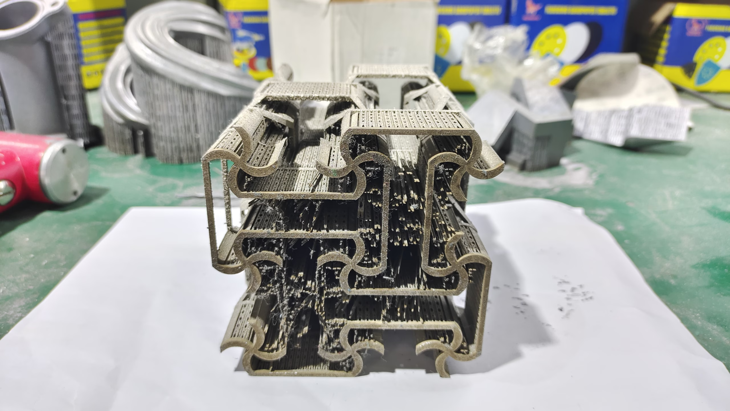
The most repeated application cases 3d printing in oil and gas circles involve impellers, diffusers, and burner tips. These parts carry swept blades and internal cooling or purge channels that a ball-end mill cannot reach without leaving the tool, and a printed Inconel or 17-4PH blank solves that in one setup.
The catch is the downstream work. Metal printed parts arrive with a rough surface, typically Ra 6–12 μm on as-built faces, and a seal face at that finish will leak. In our shop the printed blank goes onto a 5-axis center afterwards and we face, bore, and skim the critical surfaces to Ra 0.8–1.6 μm. Print near net, machine to tolerance.
If the blade count is low and the channels are simple, printing rarely pays. A 5-axis milled 6061 or 17-4PH impeller from solid bar is cheaper per part and you keep the grain structure.
- 1Good fitSwept blades plus internal channels, low annual volume, hard alloys
- 2Weak fitOpen geometry, high volume, or a flat mounting face that a mill handles in one pass
Valve bodies, manifolds, and hydraulic blocks
Valve bodies and hydraulic manifolds are the second cluster. A manifold that would need six drilled and plugged cross-holes can be printed as one solid body with internal routing, which removes a leak path at every plug. That is the whole argument, and it holds up when the bore diameter is above roughly 4 mm.
Below that, printed internal channels are hard to clean and hard to inspect. Trapped powder is a real failure mode in abrasive or sour service. Any printed manifold we touch gets bores reamed and counterbores faced on the CNC side so the O-ring seats and the threaded ports meet spec.
Pressure rating is the deciding factor more often than geometry. Where the part must hold a stamped rating, a machined 316L or 4140 body with a paper trail is the safer route, and print stays for prototypes and non-rated brackets.
- 1Good fitConsolidated cross-drilling, low count, prototype manifolds
- 2Weak fitBores under 4 mm, abrasive media, rated pressure envelopes
Spare parts and obsolete components
The strongest business case is not exotic geometry, it is downtime. A pump housing, a worn gear, or a discontinued bracket that used to mean a 12-week wait can be scanned, printed in a polymer for fit check, then machined from 17-4PH or 4140 for the running part. We see this pattern more than any other.
Reverse engineering works when you have the worn original or a usable drawing. Without either, tolerances are guesses, and a guess on a shaft fit is expensive. Measure first, then decide the process.
For a one-off replacement, subtractive usually wins on both lead time and surface finish. Print pays when the part has features you cannot reach, or when the material is one your mill cannot cut at the required geometry.
- 1Good fitObsolete or long-lead spares, one-off or low count
- 2Weak fitHigh-cycle wear parts, anything with a defined fatigue life
Tooling, fixtures, and drill jigs
Additive earns its place on the shop floor faster than it does downhole. Drill jigs, soft jaws, inspection nests, and fixture plates for field service are printed in ABS, PC, or PA and used the same week. No certification, no pressure boundary, no inspection report.
These parts also fail fast. A printed jig that sees daily clamp load will creep and lose its position, so we normally machine the locating surfaces in aluminium and let the print carry the body. Hybrid fixtures hold up better than either process alone.
Weight matters here too. A printed drill guide that weighs 200 g instead of 1.2 kg changes what a technician is willing to carry up a tower.
- 1Good fitJigs, nests, soft jaws, one-off handling fixtures
- 2Weak fitLoad-bearing fixtures, high-cycle clamping, anything that sets a datum for a rated part
Process pick by part characteristic
Use this as a first pass before you send a drawing out for review.
| Part characteristic | 3D printing | CNC machining |
|---|---|---|
| Internal channels under 4 mm | Difficult to clean and inspect | Drilled and reamed, verifiable |
| Swept blades, deep pockets | Built in one piece | Needs 5-axis and long reach tools |
| Surface finish as-built | Ra 6–12 μm, needs finishing | Ra 0.8–1.6 μm off the machine |
| Material range | Inconel, Ti-6Al-4V, 17-4PH | Same plus 6061, 316L, 4140, brass |
| Unit cost at 1–5 parts | High, setup is fixed | Low, no tooling |
| Unit cost at 500+ parts | Falls slowly, still high | Falls fast with fixtures |
| Tolerance on bores and faces | Post-machining required | ±0.005 mm achievable |
| Lead time, simple part | Days, plus finishing queue | 3–5 days after drawing release |
| Pressure-rated bodies | Prototype and fit check | Full material traceability |
| Replacement for obsolete spares | Fast if a scan exists | Fast if a drawing exists |
How we split print and machine work on one part
Most oil and gas parts we see are not one process. They are a printed or cast blank that gets finished on a mill. That split is where tolerance is decided, so it is worth being explicit about which faces are machined and which stay as-built.
We mark the drawing with three groups: sealing and mating faces, bores and threads, and cosmetic surfaces. Sealing faces and bores get machined. Threads get cut or, on larger ports, single-point threaded. Cosmetic surfaces can stay as-built if the customer accepts the layer texture.
Print orientation also sets the machining stock. Build a face vertically and you get a rough wall that needs 0.5 mm of stock removal. Build it flat and the top face may need almost nothing. Orientation is a machining decision as much as a print decision.
For parts that must fit an existing assembly, we prefer to print undersize and open up on the machine. Adding material is not an option after the fact.
- 1Machined after printSeal faces, O-ring grooves, bores, threads, bearing seats
- 2Left as-builtNon-critical walls, handles, cable routing, cosmetic covers
Where 3D printing still loses in this industry
Fatigue life is the honest answer. Printed metal has anisotropy and internal porosity that is hard to qualify for rotating or cyclic service, and most operators will not sign off without a large test program. If a part spins, cycles, or holds pressure, machined wrought material is the default.
Cost curve is the second limit. Printing does not get cheaper with volume the way machining does, because machine time per part stays roughly flat. Above a few hundred units of the same geometry, a printed part is almost never the low-cost option.
Inspection is the third. Internal channels in a printed body are hard to verify without CT, and CT on a large part is neither cheap nor fast. A machined body with drilled cross-holes can be checked with a borescope and a pin gauge in minutes.
None of this means skip printing. It means use it where geometry or lead time is the constraint, and machine the rest.
One more practical point for sour or abrasive service: trapped powder and rough internal walls both give particles somewhere to sit. If the fluid path matters, the internal surface needs a finish step, and that step has to be planned before the part is built.
- 1Rotating or cyclic serviceMachined wrought stock, documented heat lot
- 2Large internal channelsCT or destructive section, budget for both
- 3Few hundred units and upFixtured CNC run, not print
Questions engineers ask next
Can you machine a printed metal part to a sealing surface finish?
Yes. We treat the printed blank as raw stock and machine the seal faces, O-ring grooves, and bores on a 5-axis center.
Typical result on those faces is Ra 0.8–1.6 μm, and fine finishing can reach Ra 0.2–0.8 μm when the drawing calls for it.
What materials can you cut for oil and gas parts?
Stainless 303, 304, 316, 316L, 17-4PH, 420 and 440C; alloy steels 4130, 4140, 4340 and 1018; aluminium 6061-T6, 7075 and 6082; plus titanium TC4 and Inconel.
We also run beryllium copper and C36000 brass for wear and bushing parts.
Do you have a minimum order quantity for a replacement part?
No minimum. One prototype up to 10,000+ piece runs are both fine.
For a single replacement part, send a drawing or a scan and we will say whether print or machine is the faster route.
How fast can a printed-and-machined part ship?
Quotation and free DFM analysis come back within 12 hours, and production can start within 24 hours of release.
Machined parts typically ship in 3–5 days. Printed blanks that need post-machining add the build time on top, which we confirm before you commit.
Can you work from a scan of a worn part with no drawing?
Yes, but we need the critical dimensions identified before machining starts. A scan gives shape, not tolerance.
We will flag which features we can hold and which ones need a measurement from you or from the mating part.
How is confidentiality handled on drawings?
Uploads are secure and confidential. An NDA is available on request before any file changes hands.
Our quality system is certified to ISO 9001:2015, IATF 16949:2016, ISO 13485:2016 and ISO 27001:2022.
Send the part and we will tell you which process wins
Upload a drawing or a scan and get a quotation with free DFM analysis within 12 hours. No minimum order quantity.
12-hour quote100% inspectionNDA on request









