
Can CNC Directly Treat the Highlighted Mirror?
This page answers one question: whether a machining center can directly treat the highlighted mirror surface of a part, or whether the mirror finish has to come from a separate polishing step. It is written for design engineers and buyers who need to decide what to put on a drawing. After reading, you will know what a milling or turning center can hold, where it stops, and how to split the work between machining and finishing.
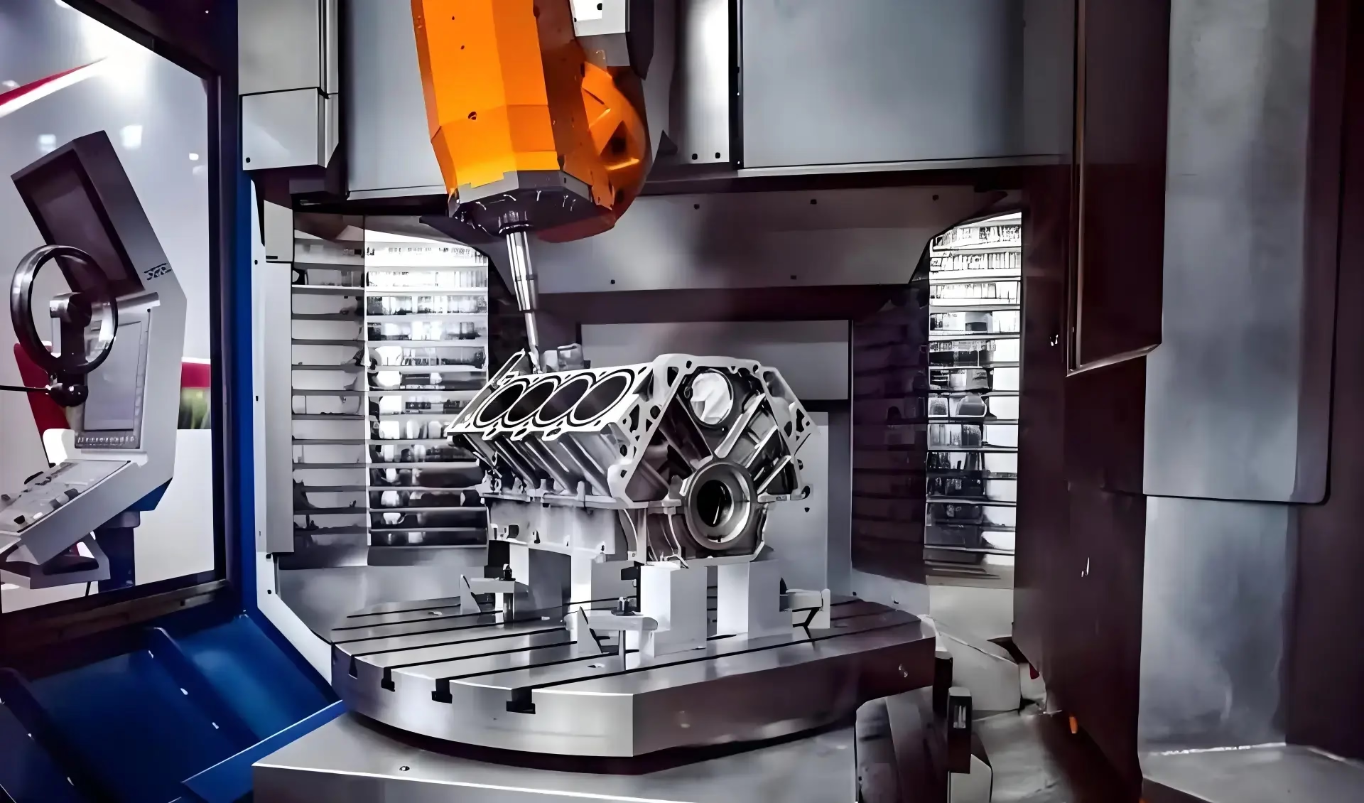
What machining can and cannot do to a mirror surface
A single-point tool can leave a very fine surface, but it does not replace polishing in every case.
Where a milling or turning center reaches its limit
The practical ceiling of a cutting tool depends on the tool edge, the material and the rigidity of the setup. On aluminium 6061, 2024 and 7075, a diamond or PCD insert run at high spindle speed can hold Ra 0.2–0.8 μm across a face. On brass C36000 and beryllium copper the numbers are similar. On stainless 316L or 17-4PH the same tool wears faster and the surface drifts toward Ra 0.4–0.8 μm.
Hardened steel is a different story. Above roughly 45 HRC the tool edge breaks down before the surface is bright, so the mirror has to come from grinding and polishing instead of a single pass. Titanium behaves in its own way: it galls against the tool edge, so a mirror face on TC4 (Ti-6Al-4V) usually needs a polishing step no matter how fine the cut looks under light.
Geometry matters as much as material. A flat face or a straight cylindrical bore is easy to hold. A deep pocket, a sharp internal corner or a curved free-form surface forces the tool to change direction, and the tool marks show up as scattered light. A radius of 0.5 mm or smaller at the bottom of a pocket cannot be cut clean by a large tool, so the surface ends up with visible steps.
The machine itself sets the floor. Our 16 simultaneous 5-axis machining centers and 16 mill-turn centers hold ±0.005 mm, which keeps the form accurate, but accuracy is not the same as optical smoothness. Spindle runout, tool holder balance and thermal drift all print into the surface at Ra 0.2 μm. That is why we inspect the finish, not just the size, before a mirror part ships.
- 1Faces and boresEasiest to bring to a bright finish directly on the machine.
- 2Deep pockets and sharp cornersTool marks and steps are hard to avoid; polishing usually follows.
- 3Hardened steel above 45 HRCGrinding and polishing replace the single-point cut.
- 4Titanium and high-nickel alloysGalling and edge wear force a separate polishing pass.
When a separate polishing step is the right call
If the drawing says Ra 0.05 μm or a reflectivity percentage, the part needs more than a cutting pass. Diamond turning can reach Ra 0.01–0.05 μm on non-ferrous metals, but it is a dedicated operation with its own machine, tool and environment. For most parts, the cheaper route is to cut close and then polish the specific face that has to reflect.
Polishing is not free of risk. Mechanical buffing rounds sharp edges and can pull a flat face out of tolerance if the operator is not careful. Chemical polishing removes material evenly, which is good for complex shapes but hard to control on a part with tight wall thickness. Electropolishing on stainless improves brightness and removes a thin surface layer, but it will not fix a wavy face.
A workable sequence is: rough the shape, semi-finish, cut the mirror face as fine as the tool allows, then polish only that face. Keep the polished area small. If the drawing marks the whole part as mirror, cost climbs fast because every surface has to be handled by hand. Mark only the functional optical face and let the rest stay at Ra 0.8–1.6 μm.
We often get parts where the mirror callout sits on a face that nobody will ever look at. Ask what the surface has to do: reflect a laser, seal against a gasket, or simply look good in a product photo. The answer decides whether a polished face is needed at all.
Material and surface: what to expect from a direct cut
Values below describe what a fine cutting pass can hold before any polishing step.
| Material | Direct cut Ra | Polishing after cut | Notes |
|---|---|---|---|
| Aluminium 6061 / 7075 | Ra 0.2–0.8 μm | Often optional | Diamond or PCD tool, high spindle speed |
| Brass C36000 | Ra 0.2–0.8 μm | Often optional | Free-cutting, holds a bright face well |
| Stainless 316L / 17-4PH | Ra 0.4–0.8 μm | Usually needed | Tool wear shifts the finish over a run |
| Steel above 45 HRC | Ra 1.6–3.2 μm | Required | Grinding and polishing replace the cut |
| Titanium TC4 | Ra 0.4–0.8 μm | Required | Galling marks the face even on a fine pass |
| PMMA / PC | Ra 0.2–0.8 μm | Required | Heat and chip welding leave haze |
How to write the callout so the shop can hold it
Put the Ra value on the specific face, not on the general tolerance block. A note that says all surfaces are Ra 0.2 μm turns a simple part into a hand-polishing job and multiplies the cost. A leader line to one face tells the machinist exactly where to spend time.
Say what the surface is for. A sealing face needs flatness and a controlled Ra, not maximum shine. An optical face needs low waviness and a clean surface, and it may also need a protective coating. If the part is a mold insert, the mirror face may need to survive thousands of shots. Each case points to a different finish.
Add the direction of the tool marks if it matters. On a turned face, marks run in circles; on a milled face, they run in overlapping arcs. If light has to scatter in one direction, the tool path has to follow. We can program the path to match, but only if the drawing says so.
Keep the mirror face reachable. A polished face inside a deep bore or behind a shoulder cannot be reached by a buffing wheel, and hand work there is slow and uneven. If the design allows a small radius or an open approach, the finish gets better and the price gets lower.
Questions engineers ask about mirror surfaces
Does a mirror finish always need a separate polishing step?
No. On aluminium, brass and some copper alloys, a fine cutting pass with a diamond or PCD tool can reach Ra 0.2–0.8 μm, which reads as a bright mirror under normal light.
Once the target drops below Ra 0.1 μm, or the part is steel, titanium or a plastic, a separate polishing or lapping step is normally required.
Can a 5-axis machine hold a mirror finish on a curved surface?
It can hold the form to ±0.005 mm and leave a bright surface, but a curved face is harder than a flat one. The tool changes direction constantly, so the marks form a pattern that shows as scattered light.
For a curved optical face, we usually cut close and then polish with a matching lap or a small wheel that follows the curve.
Will polishing change the part dimensions?
Yes, by a small amount. Mechanical polishing removes a thin layer, typically a few micrometres, and it can round a sharp edge.
If the mirror face is also a tolerance face, tell us the allowed stock for polishing so we can leave it on the cutting program.
What Ra can a diamond-turned face reach?
On non-ferrous metals, diamond turning can reach Ra 0.01–0.05 μm, which is well beyond a standard milled or turned finish.
It is a dedicated operation with its own machine, tool and temperature control, so it is reserved for optical parts where the drawing demands it.
Do you offer polishing as a service on its own?
Yes. Polishing, bead blasting, brushing and tumbling are part of our part surface finishing service, and they can run on parts we machined or on parts you send in.
We check the finish and the key dimensions after polishing and report the results on request.
How do certifications affect a mirror job?
For medical and automotive parts, the process has to be documented. Our quality system is certified to ISO 9001:2015, IATF 16949:2016, ISO 13485:2016 and ISO 27001:2022.
That means the polish step, the inspection and the material trace are recorded, not just the final look of the part.
Send us the face that has to reflect
Tell us the material, the Ra target and the face that matters. We send a quote and a free DFM analysis within 12 hours.
12-hour quote100% inspectionNDA on request









