
China CNC Prototype Service
This page explains how a China CNC prototype service turns a CAD file into a functional metal or plastic part, and what to check before you send a drawing. It is written for design engineers and sourcing staff who need to judge fit, tolerance and material before committing to tooling.
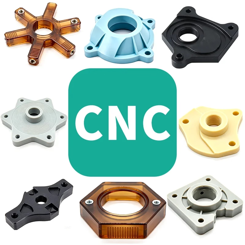
What a CNC prototype actually is
One part cut from solid stock, measured against your drawing, shipped before you cut a mold.
When to machine a prototype instead of molding it
A CNC prototype is a real part cut from solid stock on a computer-controlled mill or lathe, driven directly by your CAD data. No tooling is made, so the geometry can change between revision A and revision B without scrapping a mold. That is the main reason engineers order machined prototypes before injection molding, die casting or forging.
The trade-off is unit cost. Machining is cheap at one piece and expensive at 50,000 pieces; molding is the reverse. As a rough rule, machined prototypes stay the better choice below a few hundred units, and often well beyond that when the part is large, has tight tolerances, or is still changing.
A China CNC prototype service also covers the case where the part will never be molded at all. Bracket runs, test rigs, end-effector plates and one-off fixtures are frequently machined in the final production process because the volume is low and the tolerance is tight. In that case the prototype and the production part are the same thing, made the same way.
What you get back is not a model. It is a part you can bolt onto an assembly, pressurize, spin, drop or run on a dyno. Surface finish is a real machined finish, threads are cut threads, and the material is the material you specified. That matters when the test result has to mean something.
- 1Good fitComplex 3D contours, tight bores, low to mid volume, design still moving
- 2Poor fitThin hollow shells with uniform 1 mm walls at 100,000 units per year
- 3Also goodOne-off fixtures and test rigs that will never go to tooling
- 4Watch outInternal sharp corners a cutter cannot reach; add a radius or split the part
Five-axis work and why it matters on prototypes
Most prototype parts can be cut on a three-axis mill. You clamp the block, the tool moves in X, Y and Z, and you flip the part for the back side. The limit appears when the part has angled faces, deep pockets on more than one plane, or features that must stay aligned to each other within a few microns.
A five-axis machine tilts the tool or the table, so the cutter reaches the feature in one setup. Setup count is where prototype error creeps in. Every re-clamp adds a datum shift, and a datum shift on a prototype usually means a phone call and a rework loop. On a 16-machine five-axis group, a part that would need four setups on a three-axis mill can often be finished in two.
The practical gains are consistent wall thickness on curved housings, clean blending on impellers and turbine-like shapes, and port geometry that a straight tool cannot reach. The cost is programming time, which is why five-axis is worth it on a complex part and wasted on a flat plate.
GreatLight runs 16 simultaneous 5-axis machining centers, 12 four-axis mills, 27 three-axis machines and 16 mill-turn centers in Dongguan. Maximum processing size is 4,000 mm, with common travels of 750 × 1,150 × 550 mm and 600 × 600 × 600 mm. A Ø400 mm rotary table covers round work that would otherwise need a second lathe setup.
Machine choice by prototype geometry
Pick the axis count from the part, not from the price list.
| Prototype feature | Suggested setup | Why |
|---|---|---|
| Flat plate, holes, pockets from one side | 3-axis mill | One datum, no re-clamp, fastest cycle |
| Part needs a flip for the back side | 3-axis, two setups | Add a dowel pin or tooling hole for repeat location |
| Angled faces or pockets on two planes | 4-axis with rotary table | Cut both planes without releasing the vise |
| Curved housing, impeller, port, deep blended pocket | 5-axis simultaneous | Reaches the feature in one setup, keeps wall thickness even |
| Shaft with milled flats and a turned diameter | Mill-turn center | Turning and milling in one program, one datum |
| Ø400 mm flange with bolt circle | Rotary table | Indexed holes and face cut in one clamping |
Tolerances, materials and what to put on the drawing
GreatLight holds ±0.005 mm (±0.0002 in) on machined features, with fine finishes down to Ra 0.2–0.8 μm and typical high-quality finishes at Ra 0.8–1.6 μm. As-machined surfaces sit at Ra 1.6–3.2 μm. Those numbers are achievable, but not on every feature of every part. A 300 mm long aluminum bracket with a ±0.005 mm callout on the overall length will cost more than the same bracket toleranced at ±0.05 mm, and the tight callout may not be measurable in a normal shop environment.
Tolerance the features that mate. Bore diameters, bearing seats, dowel holes and sealing faces deserve tight numbers. Cosmetic outer surfaces and clearance holes usually do not. A drawing with five tight dimensions and forty loose ones is easier to quote, easier to inspect and less likely to come back with a deviation report.
Material choice drives both the cut and the test. Aluminum 6061-T6 and 7075 machine cleanly and are the default for housings and brackets. Stainless 303 and 316L cover food and medical prototypes; 17-4PH is common where strength and corrosion resistance both matter. Titanium TC4 (Ti-6Al-4V) and Inconel are cut on the five-axis group with slower feeds and more tool wear, which shows up in the price. Plastics such as POM, PEEK, PC and ABS are used for snap fits, covers and low-load parts.
Most prototype parts get a finish before they ship. Anodizing in clear, color, hardcoat or conductive types is the common choice on aluminum. Electroless nickel, zinc, silver and gold plating cover wear and conductivity needs. Bead blasting, tumbling, brushing and polishing change the surface before plating. Laser marking works down to a minimum character height of 1.5 mm, so keep part numbers and logos at that size or larger.
- 1Tight where it matesBearing seats, dowel holes, sealing faces, gear bores
- 2Loose elsewhereClearance holes, outer cosmetic faces, non-critical steps
- 3Say the standardISO 2768 or ASME Y14.5; mixed standards slow the quote
- 4Note the datumA clear datum scheme lets inspection match your design intent
From upload to shipped parts
A prototype order starts with a 3D file and a 2D drawing. If the drawing is missing, we work from the model and flag the features that have no tolerance callout. Within 12 hours you get a quotation and a free DFM analysis: thin walls, unreachable corners, thread depths that a tap cannot reach, and any feature that will need a second setup. That review is the cheapest place to fix a design.
Once the quote is approved, production can start within 24 hours. Parts ship in 3–5 days for most prototype geometries. Long parts, exotic alloys and multi-step finishing add time, and we say so in the quote rather than after the fact. Historical late-delivery probability sits below 2%.
Inspection is not optional here. Every part gets a raw material check, in-process monitoring and a final inspection before shipment, so 100% of parts are inspected. Reports are available on request, including dimensional reports and material certificates. For a prototype that will be used in a validation test, ask for the report with the part.
Confidentiality is handled the same way as production work. Uploads are secure and confidential, and an NDA is available on request before you send the first file. There is no minimum order quantity, so the same channel handles one prototype or a 10,000+ part run when the design freezes.
- 1SendSTEP or IGES model plus a PDF drawing with datums and tolerances
- 2Get backQuote and DFM notes within 12 hours
- 3ThenProduction starts within 24 hours of approval
- 4ShipMost prototype parts ship in 3–5 days
What drives the cost of a prototype part
Prototype pricing follows setup time and material, not part count. A part that fits in one vise and needs one program is cheap per unit even in titanium. A part that needs four setups, a custom soft jaw and a hand blend at the end is expensive even in ABS. When a quote looks high, the reason is usually in the setup list, not the material cost.
Wall thickness and depth-to-diameter ratio are the two numbers that most often force a redesign. A pocket 10 mm wide and 80 mm deep needs a long, thin cutter that deflects, so the shop has to run light passes and the cycle time climbs. Widening the pocket to 14 mm or reducing depth to 60 mm can cut the machining time substantially without changing function.
Prototype parts are also where you decide whether the design can be molded later. Draft angles, uniform walls, fillets and rib placement carry over to injection molding and die casting. Adding them at the prototype stage costs a few minutes of CAD time; adding them after a mold is cut costs a mold rework.
- 1Setup countEach re-clamp adds cost and a datum shift risk
- 2Pocket depthKeep depth-to-width under about 4:1 where possible
- 3TolerancesTight callouts on long dimensions multiply inspection time
- 4FinishingMulti-step plating and polishing add days, not just cost
Prototype questions engineers ask
Can you machine my prototype without a 2D drawing?
Yes. A STEP or IGES model is enough to quote and cut. We will flag features that carry no tolerance callout and suggest values based on how the part mates.
For anything with a bearing seat, seal groove or press fit, a drawing with datums is faster and avoids a second round of questions.
What is the smallest feature you can cut?
It depends on the material and the depth. Small end mills reach a few tenths of a millimeter in diameter, but only at shallow depth in soft material. Deep narrow slots are the usual limit.
Send the geometry and we will tell you whether the feature can be cut as drawn or needs a radius, a wider slot, or an EDM-style approach.
Do I need a five-axis machine for my part?
Usually not. Flat plates, simple housings and two-sided parts run fine on three-axis or four-axis machines, and the quote is lower.
Five-axis pays off when the part has angled faces, blended curves or features that must stay aligned after several setups. If your part has any of those, say so in the RFQ.
How do you handle my CAD files and IP?
Uploads are secure and confidential. We can sign an NDA before you send files, and the NDA page is linked from the quote form.
Files are used only for quoting and manufacturing your part. If you need the files deleted after the run, tell us in writing with the order.
Can the prototype be made in the same material as production?
Yes, and it usually should be. Aluminum 6061-T6, 7075, stainless 303/316L/17-4PH, steel 4140, titanium TC4, POM, PEEK, PC and ABS are all stocked for prototype work.
Using the production alloy means the test result transfers. A 6061 prototype that validates a 7075 production part may behave differently under load.
What happens if a dimension is out of tolerance?
Final inspection catches deviations before shipment, and a dimensional report is available on request. If a part is out of print, we tell you before it ships rather than after.
On prototype quantities, a rework or remachined part is normally the fastest route, and the decision is made with you.
Send a drawing, get a quote and DFM notes
Upload your CAD file and we return a quotation with DFM feedback within 12 hours. Every part is inspected before shipment, and an NDA is available before you send the first file.
12-hour quote100% inspectionNo MOQNDA on request









