
CNC Lathes vs Milling Machines: Key Differences
Both cut metal with a computer-controlled tool, but one spins the part and the other spins the cutter. That single difference decides which machine a part goes on. This page compares workholding, axes, geometry limits, and cost drivers so you can route a part with confidence.
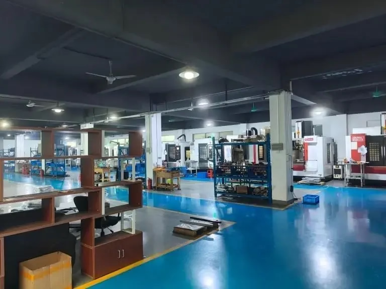
CNC lathes vs milling machines at a glance
Use this table to shortlist a process before you read the detail below.
| Point | CNC lathe (turning) | CNC milling machine |
|---|---|---|
| Motion | Workpiece rotates; tool feeds | Tool rotates; workpiece is fixed |
| Typical axes | X and Z, plus C or Y on live-tool lathes | X, Y and Z, plus two rotary axes on 5-axis |
| Best geometry | Cylinders, cones, threads, bores | Pockets, slots, flats, freeform surfaces |
| Symmetry | Axially symmetric parts | No symmetry required |
| Tooling | Single-point inserts, drills, taps | End mills, face mills, drills, ball nose |
| Setup base | Chuck or collet, one primary datum | Vise, fixture plate, or tombstone |
| Cycle behavior | Continuous cut, low idle time | Many passes, tool changes add time |
| Typical parts | Shafts, bushings, fittings, pins | Housings, brackets, manifolds, plates |
| Tolerance reach | ±0.005 mm on stable diameters | ±0.005 mm on milled features |
| Cost driver | Bar stock and cycle time | Fixture cost and setup count |
Why the motion difference decides the part
On a CNC lathe the workpiece turns and the cutting tool travels along the rotating surface. The tool only has to reach the outside diameter, so a single pass removes a continuous chip around the whole circumference. That is why turning holds tight roundness and concentricity without much effort.
On a CNC milling machine the workpiece stays clamped and a multi-flute cutter spins at high rpm. The tool has to move to every feature, so the machine spends time accelerating, cutting, retracting and changing tools. Every pocket and corner is a separate toolpath.
This is the practical test. If the part is mostly a body of revolution, with threads or a bore running down its center, it belongs on a lathe. If the part has flat faces, pockets or holes that sit at angles to each other, it belongs on a mill.
Some parts are both. A hydraulic manifold might start as a turned blank and then move to a mill for the port faces. Routing work this way keeps the tight diameters on the lathe and the flat features on the mill.
- 1Lathe defaultRound parts with one dominant axis of symmetry.
- 2Mill defaultPrismatic parts where flat datums drive the drawing.
- 3Split routingTurn the blank first, then mill the features that cannot be turned.
Axes, workholding and what that means for your drawing
A basic lathe works on two axes. X moves the tool in and out, Z moves it along the part length. Add a C-axis and the spindle can index or contour, which lets a live tool drill and mill off-center on the same setup. Add a Y-axis and you can cut flats and slots without a second operation.
A basic mill works on three axes. X and Y move the tool across the table, Z controls depth. A fourth axis adds rotation about X, usually a rotary table, so you can machine four sides of a part in one setup. A fifth axis tilts the tool or the table, which reaches undercuts and angled faces.
Workholding follows the same logic. A lathe grips the part in a chuck or collet, so the turned diameter is the datum. A mill clamps the part in a vise or on a fixture plate, so the first machined face becomes the datum for everything after it.
The number of setups is the real cost line. Each new setup adds a datum transfer, and each datum transfer adds error. If a part needs five faces machined, five-axis or a mill-turn center usually wins on both accuracy and hours.
- 12-axis latheOutside diameters, faces, threads, and center bores.
- 2Live-tool latheAdds cross-drilled holes and milled flats on the same setup.
- 33-axis millFlat plates and housings that need one or two setups.
- 45-axis millAngled features and undercuts in a single setup.
Which geometry suits which process
Turning suits anything generated by rotating a profile. Shafts, pins, bushings, spacers, valve bodies, and threaded fittings are all natural lathe parts. Deep bores are easier on a lathe because the tool enters along the centerline and the part supports the cut.
Milling suits geometry that is not symmetric. Brackets, plates, heat sinks, enclosures, and engine covers all need flat faces and pockets that a single-point tool cannot produce. Milling also handles sharp internal corners better when you can use a small-diameter cutter.
There are limits on both sides. A lathe struggles with a rectangular block because the interrupted cut pounds the insert and the corners leave the tool unsupported. A mill struggles with a long slender shaft because the part deflects under cutting force and the diameter wanders.
Slender turned parts need support. On a lathe, a tailstock or steady rest holds the free end, which keeps deflection inside the tolerance band on long shafts. On a mill, a slender part needs a support block or a sacrificial bridge, or you accept chatter and scrap it.
- 1Turn itCylindrical, conical, threaded, or bored along one axis.
- 2Mill itFlat, prismatic, pocketed, or angled relative to a flat datum.
- 3Neither aloneTurn the round body, then mill the flats and bolt patterns.
Tolerances, surface finish and inspection
Turning holds diameter tolerance well because the tool stays engaged and the spindle is rigid. On stable materials a lathe reaches ±0.005 mm on diameters and Ra 0.8–1.6 μm as machined. With a finishing pass and the right insert, Ra 0.2–0.8 μm is achievable on a turned surface.
Milling tolerance depends on feature type. A bored hole on a mill can match turning because it is still a rotating cut. A long unsupported wall cannot, because cutter deflection grows with tool length. Thin walls in aluminium often move after clamping is released, so we plan a roughing pass, a stress-relief pause, and a light finish pass.
Surface finish is directional. Turning leaves a fine helical pattern along the axis. Milling leaves a scalloped pattern from the cutter path. If the drawing calls out a sealing surface, we match the process to the required lay, not just the Ra number.
Inspection follows the same split. Turned diameters are checked with micrometers and bore gauges. Milled features are checked on a CMM against the datum scheme. We do 100% inspection before shipment and keep reports on request.
- 1Turned diameter±0.005 mm with a stable insert and rigid setup.
- 2Milled wallTolerance widens as wall thickness drops below 1 mm.
- 3Sealing faceMatch the surface lay, not only the Ra value.
Cost drivers and when to split the work
Lathe cost scales with bar stock and cycle time. Setup is short because a chuck or collet holds most round parts with one datum. For runs from a single prototype to 10,000+ parts, turning is usually the cheaper route for round geometry.
Mill cost scales with fixture design and setup count. The first article on a new fixture takes longer because the datums must be established and proven. Once the fixture is set, the per-part time drops, so milling rewards volume on the same part number.
Split routing adds a handling step but can remove a whole operation. A mill-turn center machines a turned body and its milled features in one program, which removes one datum transfer and one queue. We run 16 mill-turn centers for exactly this case.
Watch the batch size. A one-off bracket is often cheaper milled from plate than turned and milled. A 5,000-piece fitting is almost always turned from bar, then finished on a second spindle. The crossover point depends on where the round features stop and the prismatic features start.
- 1Low volumePick the process that needs the fewest setups.
- 2High volumeInvest in the fixture and amortize it over the run.
- 3Mixed geometryMill-turn removes a datum transfer and a queue.
Which one should you choose?
If the part is a body of revolution with threads or a center bore, choose the lathe. If the part is defined by flat faces, pockets or angled holes, choose the mill. When both sets of features exist and volume justifies it, route the job through a mill-turn center and stop paying for the second setup.
CNC lathes vs milling machines: common questions
Can a CNC lathe cut flats and slots?
Yes, if it has a C-axis and live tooling. The spindle indexes to a position and a driven tool mills the feature while the part is still in the chuck.
The limit is reach and rigidity. Live-tool lathes handle cross holes, flats, and keyways well, but a deep pocket or a large face is still faster on a mill.
Is milling more accurate than turning?
Not in general. Both reach ±0.005 mm when the setup is rigid and the tool is sharp. The difference is where each process is stable.
Turning holds diameter and roundness on a rotating part. Milling holds position and profile on a fixed part. Pick the process whose stable direction matches your critical dimension.
What is a mill-turn center and when is it worth it?
A mill-turn center combines a rotating spindle for turning with live tooling and often a Y-axis or B-axis for milling. One program, one setup, one datum.
It pays off when a part needs tight turned diameters and milled features that must stay in the same relationship. Removing the second setup removes the datum transfer that usually causes the mismatch.
How do I decide for a one-off prototype?
Count the setups. The process that finishes the part in fewer setups is almost always cheaper at quantity one.
If the part is round with a few cross holes, a live-tool lathe does it in one. If it is a plate with pockets on two faces, a 3-axis mill with a flip does it in two.
Do you machine both processes in-house?
Yes. We run 127 high-precision CNC machines, including 16 simultaneous 5-axis machining centers, 12 four-axis mills, 27 three-axis machines, and 16 mill-turn centers.
That mix lets us route a part to the process it suits instead of forcing it onto one machine. The maximum processing size is 4,000 mm.
What materials can both processes handle?
Aluminium 6061, 7075 and 6082, stainless 303, 304, 316L and 17-4PH, steels such as 1045 and 4140, plus brass, titanium and engineering plastics.
Hardened tool steel and nickel alloys cut on both, but we slow the parameters and plan extra passes. Send the drawing and we will confirm the route with the quote.
Send the drawing and we will pick the route
Upload your file and get a quotation with a free DFM analysis within 12 hours. No minimum order quantity, from one prototype to 10,000+ parts.
12-hour quoteNo minimum order quantity100% inspection
More process notes from the floor
We publish setup notes, tooling trials and inspection data from the factory floor.











