
3D Printing vs CNC: Key Differences Engineers Should Know Before Choosing
Both processes turn a CAD file into a real part. They get there in opposite ways, and that changes what the part can do. This guide is for design engineers and buyers comparing additive and subtractive options for metal and plastic parts, and it covers the differences that actually decide the quote.
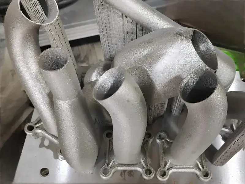
Two processes, two sets of trade-offs
The additive vs subtractive differences that matter are tolerance, material structure, geometry limits and how cost scales with quantity. Work through those four and the choice usually makes itself.
Additive builds up, subtractive cuts away
Additive manufacturing lays down material layer by layer until the shape is complete. Metal powder bed fusion, directed energy deposition and resin-based processes all share that logic. Because nothing is removed, a part can carry internal channels, lattice cores and undercuts that no cutter can reach.
Machining starts with a solid billet and removes material with rotating tools. Three-axis work handles flat pockets and drilled holes. Four-axis and simultaneous 5-axis work reach compound angles and contoured surfaces in one setup. The cutting tool must physically enter the feature, so the geometry has to leave it a path.
That single difference drives most of the rest. Additive starts free of tool access limits but ends with layer lines and directional properties. Subtractive starts with tool access limits but ends with a homogeneous, fully dense body and a surface that comes off the machine close to final size.
- 1Additive strengthBuild direction affects tensile properties; parts can be anisotropic unless heat treated or HIPed.
- 2Subtractive strengthWrought stock keeps its grain structure; no layer boundaries or internal voids.
- 3Feature accessInternal channels favor additive; sharp corners and deep threads favor machining.
- 4SetupAdditive is largely setup-free after slicing; machining needs workholding and datums.
Tolerance, finish and geometry limits
Typical figures for production work. Actual values depend on material, feature size and orientation.
| Factor | 3D printing | CNC machining |
|---|---|---|
| Achievable tolerance | ±0.1 mm typical, ±0.05 mm best case | ±0.005 mm |
| Surface finish | Ra 6–15 μm as built | Ra 0.8–1.6 μm standard, Ra 0.2–0.8 μm fine |
| Minimum wall | 0.4–1 mm depending on process | 0.5–0.8 mm, deeper pockets need more |
| Internal channels | Yes, including curved and branching | Only straight drilled holes, no bends |
| Sharp internal corners | Limited by melt pool or cure | Tool radius applies, e.g. R0.5–R3 |
| Material density | 97–99.5% after sinter, HIP raises it | 100%, homogeneous |
| Part size | Build chamber bound | 4,000 mm maximum processing size |
| Cost curve | Flat with complexity, high per part | Falls sharply with volume |
What each process can and cannot hold
Machining covers the full alloy range: aluminium 6061 and 7075, stainless 303 and 17-4PH, 4140 and 4340 steel, titanium TC4, Inconel, beryllium copper and engineering plastics such as POM, PEEK and HDPE. The billet is already at full density, so no sintering step stands between the design and the finished properties. Heat treatment, anodizing, plating and bead blasting all apply normally.
Metal printing uses a narrower field. Ti-6Al-4V, 316L, 17-4PH, Inconel 718 and a few aluminium alloys like AlSi10Mg cover most work. The as-built surface is rough and needs support removal, then often machining or tumbling to hit a usable finish. A printed part that needs a seal face or a bearing bore usually gets those features cut anyway, which is where hybrid routing starts.
Plastics split along the same line. FDM and SLA serve fit checks, jigs and low-stress covers well. A printed PEEK or carbon-filled part can survive heat, but its layer bonds still set the failure mode. When the part carries load, sees pressure or must hold a thread under torque, machined stock is the safer call.
Where the cost curves cross
Additive pricing tracks machine time, not part count. One complex bracket costs roughly the same as ten, because each build cycle is paid for once. That makes printing attractive for a single prototype with organic ribs or a manifold with internal flow paths. There is no tooling to amortize.
Machining pricing works the other way. The first part carries programming, fixturing and setup. Each additional part adds only cycle time and material, so unit cost drops fast across a run. For a simple turned bushing at 500 pieces, machining wins by a wide margin.
The crossover sits somewhere between 10 and 100 units for most metal parts, and it moves with geometry. A part with many machined features pushes the crossover up. A part with one feature that no cutter can reach may stay printed at any volume, or get printed and then finished on a mill.
There is no minimum order quantity here, so a single prototype and a 10,000-part run both go through the same shop. Quotation and a free DFM analysis come back within 12 hours.
How to decide on a real part
Start with the function. If the part carries a load, seals a fluid, holds a press fit or threads into another component, the tolerance and density argument points to machining. If the part routes air or coolant, damps vibration, or exists to check a shape in someone's hand, printing usually gets there faster and cheaper.
Then look at the geometry. Curved internal channels, lattice cores and trapped features are additive territory. Sharp corners, deep bores, fine threads and tight flatness are machining territory. A part can need both, and that is normal. Printed near-net shapes that get their critical faces machined are common in aerospace and medical work.
Finally, count the parts. One to ten favors printing unless tolerance rules it out. A hundred or more favors machining unless the geometry rules it out. Between those numbers, get both quotes and compare the delivered part, not just the unit price.
Industries with strict traceability, such as aerospace, medical devices and automotive, usually require machining for the structural parts. Powder provenance, porosity and post-processing all need documentation, and a machined billet from certified stock keeps that chain short.
Common questions
Can a 3D printed part hold ±0.005 mm?
Not as printed. Metal powder bed fusion typically lands within ±0.1 mm, and ±0.05 mm on a good day with a small part and a stable orientation.
If the drawing calls for ±0.005 mm, those features get machined after printing. We print near-net, then set up on the printed body and cut the critical bores, faces and threads.
Is printed metal as strong as machined metal?
The alloy can be the same, but the microstructure is not. Layer-wise melting leaves some porosity, usually 0.5–3%, and properties differ along the build direction.
Hot isostatic pressing closes most of the porosity and heat treatment evens out the grain structure. Even then, a wrought billet gives more predictable fatigue behavior, which matters for rotating or pressure-loaded parts.
Which process is cheaper for 50 identical brackets?
Usually machining. The first part pays for the setup, and the remaining 49 add cycle time only.
Printing charges machine time per build, so 50 brackets may need several builds and the price stays close to 50 times the single-part cost.
Can I get internal channels in a machined part?
Straight drilled holes, yes. Cross-drilled intersections are possible with careful setup.
Curved or branching channels are not reachable with a rotating tool. Those parts are printed, or split into sections and joined.
What does the design file need before quoting?
A STEP or IGES file with tolerances on the drawing, plus the material and finish callouts. For printed parts, a native file helps with orientation decisions.
We return a DFM analysis with the quote within 12 hours. Uploads stay confidential, and an NDA is available on request.
Do you run both processes in house?
Yes. Custom 3D printing and CNC machining sit under the same roof, along with finishing, so a hybrid part does not need to travel between suppliers.
That also means the recommendation is not biased toward one route. If printing is the better answer for your part, we will say so.
Send the drawing and get a process recommendation
Upload your CAD file and we will tell you which route fits, with a quote and DFM notes inside 12 hours.
12-hour quote100% inspectionNDA on request









