
CNC machining in aerospace: how tolerances, materials and inspection really work
This page explains what changes when a machined part flies. We cover material behavior, tolerance stack, five-axis setups and the inspection chain that decide whether a bracket, fitting or housing is airworthy, and when a simpler process is the better answer.
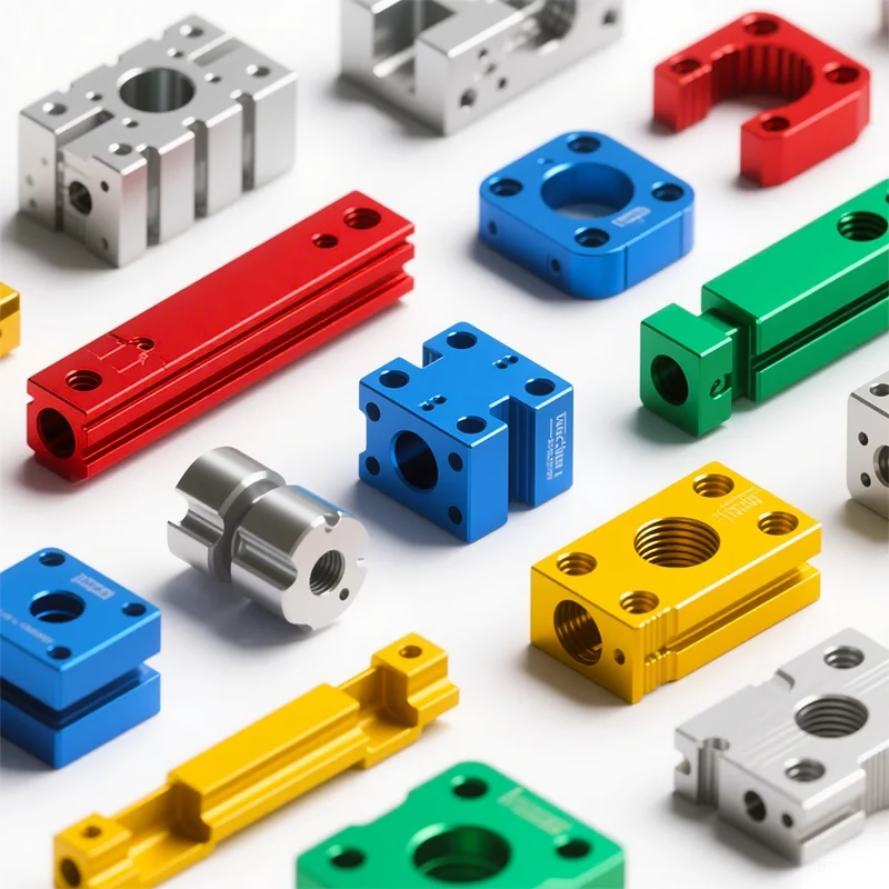
Why CNC machining in aerospace starts from wrought stock
Aerospace hardware lives with two loads at once: mechanical stress and thermal cycling. A titanium fitting on an engine pylon can swing from -55 °C at altitude to over 200 °C near a nacelle, and it does that thousands of times. Material grain direction, residual stress and surface finish all decide how long it survives. CNC machining removes material from wrought stock, so grain flow stays continuous along the load path instead of ending at a casting skin.
That is the main reason CNC machining in aerospace dominates low and medium volume work. Castings and forgings win at high volume, where tooling cost spreads over tens of thousands of parts. Below roughly 500 pieces a year, the tooling never pays back, and design changes during a program freeze would scrap it anyway. Milled and turned parts stay changeable until the drawing is released.
The trade-off is stock removal. A bracket can start as a 20 kg aluminum plate and leave the machine at 900 g. That is a lot of chips, and it costs spindle time. For thin ribs and long pockets, the cutting forces also push the part around, which is where five-axis setups and light finishing passes earn their place.
One more boundary: not every geometry should be machined. A hollow duct with internal channels, or a lattice that only exists to save weight, is often better printed and then machined only on its sealing faces and bolt holes. Machining is a finishing and interface process there, not the primary one.
Material behavior decides the cutting parameters
Aluminum 7075-T6 is the workhorse for airframe structure. It cuts fast, holds ±0.005 mm without much fuss, and has a high strength-to-weight ratio. The catch is that it is notch sensitive and corrodes without protection, so most 7075 parts get anodized or primed. 6061-T6 is easier to weld and cheaper, which makes it the pick for brackets and housings rather than primary structure.
Titanium Ti-6Al-4V (TC4) is where the process gets hard. It conducts heat poorly, so the cutting edge takes the temperature instead of the chip. Tool life drops fast above 60 m/min, and the material can work-harden if the cutter rubs instead of cuts. We run it slower, with high-pressure coolant and sharp uncoated carbide, and we accept lower material removal rates.
Inconel and other nickel alloys push that further. They hold strength at 700 °C, which is why they sit in exhaust paths, but they also gall and chatter. Rigid setups matter more than spindle speed here. A short tool, a stub holder and a full-flood coolant line do more for the result than another 1,000 rpm.
Stainless 17-4PH (SUS630) is common for actuators and fasteners because it takes heat treatment to high strength after machining. Machine it in the annealed condition, then age it. Cutting it after aging is possible but slow, and the risk of a scrapped lot goes up.
Five-axis setups reduce error stacking
Every time a part moves to a new fixture, it picks up a locating error. Three setups on a complex housing can add up to 0.03 mm before the cutter even touches metal. Five-axis machining cuts that number by reaching five faces in one setup, so the datums stay the same from the first roughing pass to the last finishing pass.
On our 16 simultaneous five-axis centers, the rotary table is Ø400 mm and the work envelope reaches 4,000 × 400 × 150 mm on the large machines. That covers most airframe ribs, brackets and long spars. Medium machines run 750 × 1,150 × 550 mm, and the compact cells handle parts under 500 mm where rigidity matters more than reach.
The limits are real. A five-axis spindle is less stiff than a three-axis one at the same size, so deep pockets in titanium still favor a three-axis machine with a short, fat tool. Thin walls under 0.8 mm deflect no matter how many axes you have; you fix them with support, not with motion.
Tool access is the other constraint. If the part has an undercut or a channel the tool cannot reach at any angle, no axis count helps. That is a design conversation, not a machining one, and it is better to have it before the drawing is frozen.
What ±0.005 mm means on the shop floor
A tolerance is a budget, not a single number. The drawing says ±0.005 mm, but that has to cover machine positioning, thermal growth, tool wear and measurement uncertainty. On a 300 mm aluminum part, a 5 °C shop temperature swing moves the material about 0.02 mm on its own. So we control temperature, and we cut finishing passes in the same thermal window as the final inspection.
Surface finish and tolerance are linked. A Ra 0.8–1.6 μm finish is typical for sealing faces and bearing bores. Ra 0.2–0.8 μm is available when a surface sees sliding contact or fatigue load, because a polished surface removes the micro-notches where cracks start. As-machined Ra 1.6–3.2 μm is fine for non-critical brackets.
Inspection closes the loop. We check incoming raw material, monitor dimensions in process, and inspect 100% of parts before shipment, with reports on request. For aerospace work, a first-article report and a dimensional report are usually part of the package, not an extra.
Here is the honest limit. Grinding, not milling, is the right answer when you need better than ±0.005 mm on a hardened bore, or when roundness matters more than position. We will say so instead of quoting a milling job that cannot hold the callout.
Traceability from stock to shipping box
Aerospace buyers do not buy a shape. They buy evidence that the shape is correct. That means the material certificate has to match the heat number on the part, and the inspection record has to match the revision on the drawing. Lose that chain and the part is scrap even if it measures perfectly.
Our quality system is ISO 9001:2015, IATF 16949:2016, ISO 13485:2016 and ISO 27001:2022. The last one matters more than people expect: aerospace drawings are controlled data, and uploads to our portal are encrypted and confidential. We sign NDAs on request before a file is even opened.
Process control is a rate, not a promise. Our qualification rate runs at 99.99%, and the historical late-delivery probability is below 2%. Those numbers come from jobs already shipped, not from a target sheet.
For prototypes and small runs, the same inspection applies. There is no minimum order quantity here, so a single first article goes through the same material check, in-process monitoring and final inspection as a 10,000-part run.
Which process fits the part you have
Read the row that matches your geometry and volume, not the one that sounds best.
| Part situation | Best process | Why | Watch out for |
|---|---|---|---|
| Bracket or rib, under 500 pcs/yr | 3-axis or 4-axis milling | Simple prismatic geometry, fast setup | Thin walls still deflect |
| Housing with features on 5 faces | 5-axis machining | One setup, less error stacking | Lower spindle stiffness |
| Long spar, 4,000 mm envelope | Large 5-axis cell | Reach plus multi-face access | Fixture cost and handling |
| Hollow duct or lattice | Additive, then CNC finishing | Internal channels cannot be cut | Machining only interfaces |
| Hardened bore, tight roundness | Grinding after machining | Better roundness and finish | Extra lead time |
| Titanium fitting, high load | 5-axis with slow parameters | Grain flow along load path | Tool wear and heat |
| Inconel exhaust part | Rigid 3-axis or 5-axis | Heat resistance, hard to cut | Chatter and galling |
| Single prototype | 3-axis or 5-axis, no MOQ | Design not frozen yet | Revisions after cutting |
The short version
Choose CNC machining in aerospace when the part carries load through continuous grain, needs ±0.005 mm on multiple faces, or is still changing shape. Choose casting or forging above roughly 500 pieces a year, and choose grinding when roundness beats position. If your geometry has internal channels, print it first and machine only the sealing faces.
Questions engineers ask next
Can you hold ±0.005 mm on a 2 m titanium part?
Not the same way as on a 300 mm aluminum bracket. Tolerance has to cover thermal growth, fixturing and tool deflection, and all three grow with part length. On long titanium parts we usually negotiate a wider callout on non-critical features and keep the tight band on the mating surfaces.
If the drawing needs ±0.005 mm across 2 m, the honest answer is to talk about datum strategy and inspection method before we quote. A CMM report on a part that long is a different job than a caliper check.
Do you machine Inconel and other nickel alloys?
Yes. Inconel and similar alloys are in our titanium and special materials list, along with TA1, TA2, TC4 (Ti-6Al-4V) and magnesium AZ31B and AZ91D.
The parameters are slower than aluminum by a large factor, and tool life is short. Expect higher cost per part and a longer cycle, not a different quality standard.
What surface finishes are available for aerospace parts?
Anodizing in clear, color, hardcoat and conductive versions, electroless nickel, zinc, silver and gold plating, powder coating, black oxide, bead blasting, tumbling, brushing and polishing.
Laser marking is available at a minimum character height of 1.5 mm, which matters if you need a part number or heat code on the surface.
How fast can a prototype ship?
Quotation and a free DFM analysis come back within 12 hours. Production can start within 24 hours, and parts ship in 3–5 days.
That timeline assumes the drawing is complete and the material is in stock. A missing datum or an unspecified thread callout will pause it.
Is my drawing safe with you?
Uploads are secure and confidential, and we work under ISO 27001:2022 for information security. An NDA is available on request and can be signed before files are shared.
We do not share customer drawings or part photos in marketing material.
Can you work from a 3D model only?
Yes, but a model without a drawing leaves tolerance decisions to us. For aerospace parts that is usually not acceptable, because the load path and the mating interface define what matters.
Send the model plus a drawing with datums and callouts, or tell us which features are critical and we will work from that.
Send the drawing, get a DFM answer in 12 hours
Upload your file and we will come back with a quotation and a free DFM analysis, covering material, setup count and the features that may not hold tolerance.
12-hour quote100% inspectionNo MOQNDA on request
More from the shop floor
We publish setup notes, tooling trials and inspection data from the factory floor.











