
CNC machining to enhance surface finish
This page explains what actually sets the surface texture of a machined face: tool geometry, feed per tooth, spindle speed, cutter runout and the finishing allowance left by the previous pass. Read it if you are specifying Ra on a drawing, deciding between one finishing pass and a secondary finishing operation, or chasing a scratch or chatter mark on a production part.
In this article
- 1
- 2
- 3
- 4
- 5
- 6
- 7
Key takeaways
What actually sets Ra on a milled face
Surface roughness on a machined face is the arithmetic mean of the profile deviations from the mean line, measured over a sampling length. On a milled surface, that profile is built from the scallops left by each passing tooth. If the cutter has four teeth and the feed is 0.1 mm per tooth, the crest-to-crest distance is about 0.1 mm regardless of how sharp the insert is.
The theoretical roughness of that scallop follows from the tool corner radius and the feed per tooth. A larger corner radius flattens the scallop, so a 0.8 mm corner at the same feed leaves a shallower profile than a 0.4 mm corner. This is why a finishing tool with a small nose radius is not automatically the better choice for Ra.
In practice the measured value is always rougher than the theoretical one. Tool runout, built-up edge, vibration and the metallurgy of the workpiece all add to the profile. On aluminium, built-up edge can double the Ra compared with a clean cut at the same parameters.
A useful way to read CNC machining to enhance surface finish is as a fight against those extra sources. The cutting parameters set the floor. Everything else decides how far above the floor you land.
- 1Theoretical RaSet by feed per tooth and tool corner radius.
- 2Measured RaTheoretical value plus runout, vibration and edge build-up.
- 3Where to look firstMeasure runout before you change a single speed or feed.
Feeds, speeds and the finishing allowance
A finishing pass should remove the damaged layer left by roughing, not just skim the top. On steel, that means leaving 0.3–0.5 mm on the walls and floor after roughing; on aluminium, 0.2–0.3 mm is usually enough because the damage depth is shallower. Cut less than that and the tool is still cutting in work-hardened or smeared material.
Spindle speed matters through cutting temperature rather than through the scallop. Running a carbide end mill too slowly in 6061 aluminium tears the surface and produces a dull, smeared finish. Running a small cutter too fast in 304 stainless work-hardens the top layer and shortens tool life without improving Ra.
Feed per tooth is the single most effective dial for finish. Halving it roughly halves the scallop height, but it also doubles the time in cut. On a 10 mm four-flute end mill in aluminium, dropping from 0.08 mm to 0.04 mm per tooth usually moves Ra from the Ra 1.6–3.2 μm band into the Ra 0.8–1.6 μm band.
Coolant strategy is often ignored. Mist coolant on aluminium finishes well and keeps chips clear. Flood coolant on stainless controls heat but can cause thermal shock on the cutting edge during interrupted cuts, which shows up as a chipped edge and a torn finish.
- 1SteelLeave 0.3–0.5 mm after roughing for the finishing pass.
- 2Aluminium0.2–0.3 mm allowance is normally sufficient.
- 3Feed per toothThe main dial for scallop height; halve it and expect a smoother face.
Why the machine and the holder matter
A rigid setup lets you use the parameters the tool was designed for. A 16 mm end mill in a shrink-fit holder on a 5-axis machine with a Ø400 mm rotary table behaves very differently from the same cutter in a worn collet chuck on a tired 3-axis. The tool is the same. The finish is not.
The holder is usually the weak link. A collet chuck with 0.02 mm runout puts most of the cutting load on one flute, and that flute leaves a bright line that dominates the Ra reading. A hydraulic or shrink-fit holder holds runout under about 0.005 mm on a good day.
Machine geometry decides whether you can reach the finish in one setup. A part with a deep pocket and a thin wall cut in two setups usually picks up a step at the joint and a different Ra on each side. Turning it on a simultaneous 5-axis center lets the tool follow the wall in one continuous pass.
Vibration is the other hidden variable. Long tools, thin floors and unsupported walls chatter, and chatter leaves a regular pattern that no parameter change will remove. Shortening the tool or adding a support often fixes what a speed change cannot.
- 1Check runout firstUnder 0.005 mm is a reasonable target for finishing holders.
- 2Fewer setupsOne continuous pass beats two blended passes for consistency.
- 3ChatterFix the setup, not the speed, when the pattern is regular.
Material behaviour and what it does to finish
Different metals respond differently to the same cutter and parameters. Aluminium 6061 and 7075 cut cleanly and take a fine finish easily, but soft grades like 5052 tend to smear and need sharper geometry and higher rake.
Austenitic stainless such as 304 and 316L work-hardens as it is cut. If the tool rubs instead of shearing, the top layer hardens and the next tooth cuts a harder, more torn surface. A heavier feed per tooth with a sharp edge often produces a better finish than a light feed with a dull one.
Titanium TC4 (Ti-6Al-4V) conducts heat poorly, so the cutting edge runs hot and tends to chip. A worn edge leaves a smeared, galled surface. Fresh inserts and generous coolant or high-pressure through-tool coolant keep Ti-6Al-4V finishes predictable.
Plastics and composites behave differently again. POM and PEEK cut cleanly with sharp, polished flutes. Carbon fibre and glass-filled grades abrade the edge quickly, so tool changes need to be scheduled by part count rather than by visible wear.
- 1Aluminium6061 and 7075 finish easily; 5052 smears more.
- 2Stainless304 and 316L work-harden; do not rub the edge.
- 3TitaniumFresh edges and good coolant control galling.
- 4CompositesChange tools on a count, not on visible wear.
When machining alone cannot hit the finish
A single machining operation has practical limits. On most metals, a well-set finishing pass lands around Ra 0.8–1.6 μm. Getting to Ra 0.2–0.8 μm in the cut is possible on aluminium and brass with a polished single-crystal or PCD tool, but on steel and stainless it becomes slow and expensive.
Geometry can block the route. A deep slot narrower than the tool shank, an internal corner with a small radius, or a hole with a high depth-to-diameter ratio may not allow the tool and the coolant to reach the surface properly. In those cases the machined finish is a compromise.
Cosmetic parts have a different problem. A machined surface shows tool marks by nature, and if the customer wants a uniform matte or a mirror look, a secondary operation is usually cheaper than trying to cut the appearance directly. Bead blasting, tumbling, brushing and polishing all change the surface in ways a cutter cannot.
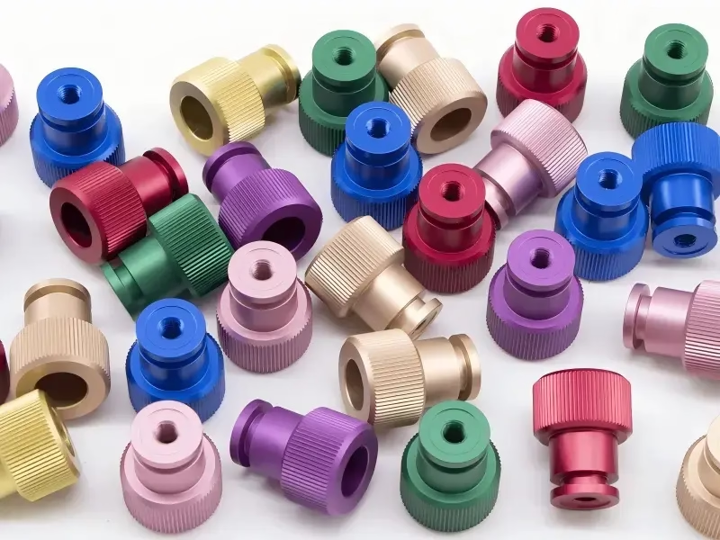
Anodizing and plating add another layer. Hardcoat anodizing builds 25–50 μm of oxide and replicates the surface underneath, so a scratch before anodizing becomes a visible scratch after anodizing. The finish has to be right before the coating, not after.
- 1Machined onlyRa 0.8–1.6 μm is a realistic target on most metals.
- 2Fine machinedRa 0.2–0.8 μm is practical on aluminium and brass.
- 3CoatingsAnodizing and plating copy the surface they sit on.
Choosing between a finishing pass and a secondary operation
Use this to decide where to spend the money.
| Route | Typical Ra | Best for | Watch out for |
|---|---|---|---|
| As-machined pass | Ra 1.6–3.2 μm | Brackets, fixtures, non-cosmetic faces | Visible tool marks on blends |
| Fine finishing pass | Ra 0.8–1.6 μm | Sealing faces, bearing bores, sliding surfaces | Longer cycle, tighter tool control |
| Polished cutting edge | Ra 0.2–0.8 μm | Aluminium and brass cosmetic faces | Not economical in steel |
| Bead blasting | Matte, Ra depends on media | Even cosmetic look over machined marks | Can round small edges slightly |
| Tumbling or brushing | Directional or satin look | Deburring plus appearance in one step | Less control on tight tolerances |
| Polishing | Mirror, low Ra | Show parts, optical housings | Labor cost, edge rounding risk |
Where the line sits
If the drawing calls Ra 0.8–1.6 μm on functional faces, a correctly set finishing pass on a rigid machine is enough; if it calls Ra 0.2–0.8 μm in steel, or the part is cosmetic and must look uniform, plan a secondary finishing step from the start rather than trying to cut the appearance.
Questions engineers ask about surface finish
Can CNC machining to enhance surface finish reach Ra 0.2 μm on steel?
It is technically possible with a very light finishing pass, a sharp edge and a rigid setup, but the cycle time and tool cost climb fast. On steel and stainless, most projects get to that level with polishing after machining rather than in the cut.
On aluminium and brass, Ra 0.2–0.8 μm from the cutter is realistic with a polished or PCD edge.
Does a slower feed always give a better finish?
No. Below a certain chip thickness the edge rubs instead of cutting, especially in stainless and titanium. That rubs work-hardens the surface and can make Ra worse. There is a working window, and it depends on the edge radius of the tool.
Why does the first part look good and later parts get rougher?
Tool wear is the usual cause. The edge radius grows, cutting pressure rises and the surface tears. In abrasive materials like carbon fibre or glass-filled plastics this happens within a small number of parts.
Runout creeping in from a loose holder or a chip trapped in the collet is the second cause.
Can anodizing hide machined tool marks?
It makes them more visible, not less. Anodizing converts the surface rather than filling it, so the oxide follows the profile underneath. Scratches, chatter and tool marks stay.
If the part will be anodized, the machined finish has to be acceptable before the coating goes on.
How do I specify surface finish on a drawing?
Call out Ra only on faces where it matters, and use the smallest number of different values you can. A blanket Ra 0.4 μm note on every face adds cost without adding function.
Where the finish is cosmetic, describe the look as well as the number, because two surfaces can measure the same Ra and look different.
What tolerance can be held alongside a fine finish?
On our 5-axis centers we work to ±0.005 mm (±0.0002 in) on critical features, and every part is inspected before shipment. Finish and tolerance are set independently on the drawing, but tight tolerance and fine finish on the same face usually means a slower, more controlled cut.
Send the drawing, get a finish plan
Upload your part and we will reply within 12 hours with a quotation and a free DFM analysis, including the finishing route we would use and the Ra we expect to hold.
12-hour quoteFree DFM analysisNo minimum order quantity
More from the shop floor
We publish setup notes, tooling trials and inspection data from the factory floor.











