
Milling CNC: how a rotating cutter removes metal
Milling CNC is a subtractive process. A spinning multi-flute cutter follows programmed paths while the part stays clamped. This page explains the mechanics, the numbers that set accuracy, and the cases where a mill is the wrong call.
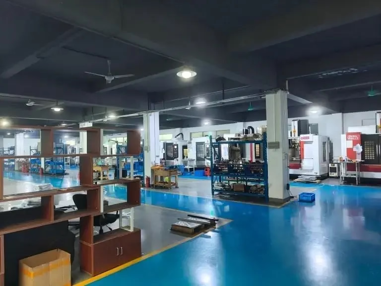
What actually happens at the cutting edge in milling CNC
Milling starts with a spinning tool, not a spinning part. The spindle turns a cutter with two to six flutes, and each flute takes a small bite as it passes the workpiece. The table moves the part along X, Y and Z so the flutes trace the surface defined in CAM. Material leaves as chips, and the shape that remains is the part.
The bite size per flute is the chip load. It is set by feed rate divided by spindle speed and flute count. Too small a chip load rubs the edge instead of cutting it. Too large a chip load overloads the flute and pushes the tool off the programmed path.
Heat is the other half of the story. Most heat should leave with the chip, not soak into the part. That is why coolant type, air blast and feed rate matter more than spindle speed alone on milling CNC work. Cutting fluid also clears chips from the flute gullet, and a packed gullet is the fastest route to a broken tool.
Every milling CNC operation has a radial and an axial depth of cut. Radial depth describes how much of the cutter diameter engages the material. Axial depth describes how deep the flute reaches on the Z axis. Shallow radial cuts with deep axial passes suit hardened material. Full-width cuts suit soft aluminum where the cutter can clear chips freely.
Tool paths: climb, conventional and corner load
Climb milling feeds the cutter into the material so the tooth enters at the thickest part of the chip. The cutting force pushes the tool away from the finished wall, and the surface comes out cleaner. Conventional milling does the opposite and tends to rub. On a manual machine with backlash, conventional milling was safer. On a ballscrew machine with preloaded nuts, climb milling is the default.
Cutter engagement stays constant in a straight line, but corners change everything. When a tool enters an internal corner, the arc of contact grows and the chip gets thicker. Programmers reduce feed in corners, or use trochoidal paths that keep engagement steady. Ignoring corner load is a common cause of chatter marks and snapped end mills.
Roughing and finishing are separate decisions. A roughing pass removes bulk material with a larger stepover and leaves stock for the finish. A finishing pass takes 0.2 to 0.5 mm radial and holds the final dimension. Trying to do both in one pass either burns the tool or misses the tolerance.
Rest material is what the previous tool could not reach. Small tools clear the corners left by large tools. Every tool change costs time, so the path planner should use the largest tool that reaches the feature before dropping to smaller diameters.
Workholding decides whether the cut is quiet
A vise holds a block on two parallel faces. It is fast and rigid, and it suits rectangular parts. A three-jaw chuck suits round stock on a mill-turn center. A vacuum plate holds thin plates that would bend under clamp pressure. Soft jaws machined to the part profile hold irregular shapes without marring the finished surface.
Thin walls are the classic milling CNC problem. Clamp pressure distorts the wall while cutting, and the wall springs back after unclamping. The part measures correct on the machine and wrong on the bench. Light finishing passes, support material left in place, and reduced clamping force all help.
Zero-point systems let a pallet move between machines without re-indicating the part. That saves setup time and keeps the datum consistent across operations. For a 4,000 mm part, the table itself becomes the fixture and the part is indicated directly.
First-article inspection checks the datum before the run starts. If the datum is off, every dimension shifts by the same amount. Catching it on part one is cheaper than catching it on part fifty.
Tolerance, finish and thermal drift
Tolerance is a range, not a target. A drawing calling ±0.005 mm on a 300 mm aluminum plate is asking the shop to hold the whole plate within a band narrower than the thermal expansion over a 5 °C shop swing. Aluminum grows about 23 μm per meter per degree Celsius. That is a real number, not a theory.
Surface finish is set by feed per tooth and tool nose radius. A finer finish needs a smaller stepover, a sharper insert and a stable setup. Ra 0.8–1.6 μm is a normal machined finish. Ra 0.2–0.8 μm needs a finishing pass and often a different tool.
Tool runout adds directly to the finished size. A cutter with 0.02 mm runout cuts 0.02 mm wider than its nominal diameter on one side. That error appears on every part in the run. Checking runout with a dial indicator before the run takes a minute.
Thermal drift moves the machine over a long run. Spindles warm up, ballscrews grow, and the first part of a shift can differ from the last. Letting the machine run a warm-up cycle and keeping the shop temperature stable reduces the spread.
When milling CNC beats turning, and when it does not
Pick the process from the part geometry, not from habit
| Part feature | Milling CNC | Turning | Why |
|---|---|---|---|
| Prismatic pockets and slots | Best fit | Not possible | Cutter reaches internal corners |
| Round shaft, Ø50 mm × 300 mm | Possible but slow | Best fit | Part spins, single-point tool |
| Thin wall under 1.0 mm | Needs support | Risky | Clamp pressure distorts the wall |
| Deep hole, 10 × diameter | Poor chip exit | Good with gundrill | Flute length limits reach |
| One-off prototype | Fast setup | Fast setup | No tooling cost either way |
| 10,000+ simple round parts | Slow cycle | Best fit | Bar feed runs unattended |
| 5-sided complex part | 16 five-axis centers | Not possible | One setup, five faces |
The short version
If the part is prismatic with pockets, flats or angled faces, mill it. If it is round and long, turn it. If it needs five faces in one setup, use a five-axis mill.
Questions engineers ask about milling CNC
How small a tool can you run?
Tools down to 0.5 mm diameter are practical in aluminum and brass. Below that, the flute is fragile and the feed per tooth gets very small.
In hardened steel or titanium, 1.0 mm is a more realistic floor. Smaller tools also need higher spindle speed to keep the chip load in range.
Does a finer finish always cost more?
Usually yes, because it needs an extra finishing pass and sometimes a different tool.
The cost step is not linear. Going from Ra 1.6–3.2 μm to Ra 0.8–1.6 μm is a small addition. Going below Ra 0.8 μm adds a separate operation.
Why does my part measure right on the machine and wrong after unclamping?
Clamp pressure is the usual cause. The wall deflects while held and springs back when released.
Check the wall thickness, reduce clamping force, and leave support material until the last pass.
Can milling CNC hold ±0.005 mm on a large part?
On small features, yes. On a 300 mm aluminum plate, thermal expansion makes it unreliable.
±0.005 mm is realistic on features under about 100 mm when the shop temperature is stable and the datum is clean.
What file format do you need for a quote?
STEP and IGES cover most parts. STL is acceptable for simple geometry but loses sharp edges.
A 2D PDF with tolerances helps. We return a DFM analysis with the quote, usually within 12 hours.
Do you mill plastics as well as metals?
Yes. ABS, PC, PMMA, POM, PA, PEEK, PP and HDPE are all routine.
Plastic needs sharp tools and higher rake angles. Melting at the cut is the main risk, so feeds run higher and depths lighter than in aluminum.
Send a drawing, get a milling CNC answer
Upload your STEP file and we return a quote plus a DFM analysis within 12 hours.
12-hour quote100% inspectionNo minimum order
More from the shop floor
We publish setup notes, tooling trials and inspection data from the factory floor.











