
CNC Plastic Prototype: How Machining Turns Resin Into a Testable Part
A CNC plastic prototype is a machined part cut from solid plastic stock, not molded. This page covers how the process works, which resins behave well on a mill, where tolerances stop being realistic, and when machining is the wrong call. Written for design and manufacturing engineers who need a functional part before committing to tooling.
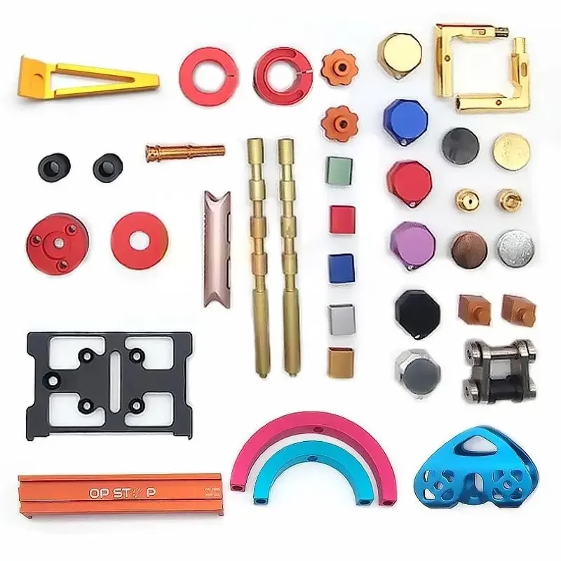
What actually happens during a CNC plastic prototype run
A CNC plastic prototype starts as a block, plate, or rod of resin. The machine does not melt or inject anything. It removes material with rotating cutters, following toolpaths generated from your CAD file. That distinction matters more than it sounds: because the part is cut from solid stock, the resin has already reached its final density and molecular orientation before the first cut.
Stock selection drives the whole run. Extruded plate is cheaper and flatter, but it carries internal stress that can bow a thin wall after machining. Cast plate costs more and machines more predictably. For a housing with a 2 mm wall, that difference shows up as warp measured in tenths of a millimeter, not thousandths.
The workflow is short. We review the model, flag features that cannot be cut, cut the toolpath, machine the part, then deburr and finish it. Quotation and free DFM analysis come back within 12 hours, and production can start within 24 hours. Most plastic prototypes ship in 3–5 days.
Cutting forces are low compared with steel, so the machine is rarely the limit. The limit is usually the resin itself: how much heat it takes at the cutting edge, how much it springs back, and how well it holds a thread.
How each resin behaves under a cutter
ABS machines like a soft, slightly gummy metal. Sharp tools and high spindle speed give a clean edge. It takes threads well and taps cleanly down to M3. Heat is the enemy: a dull cutter smears the surface instead of cutting it, and the smear is hard to sand out of a cosmetic face.
POM, also sold as Delrin, is the best all-round machining plastic. Chips break cleanly, dimensions hold, and the surface finishes well. It is the default choice for gears, cams, and sliding parts. Its low surface energy means paint and adhesive do not stick without a chemical treatment first, so do not design a POM part that needs a bonded label.
PC is tough and transparent-grade stock is available, but it scratches and stress-cracks around tight radii. PMMA gives better optical clarity and machines to a polished edge, which suits light pipes and display lenses. Both need slow feed rates and generous coolant to avoid a cloudy finish.
PA and PEEK take heat and wear. Unfilled PA absorbs moisture and grows slightly after machining, so hold critical dimensions only after the part has equilibrated. PEEK is expensive and abrasive; expect higher cost and slower cutting. Carbon fibre reinforced grades wear tools fast and leave a fuzzy edge on thin walls.
- 1Best all-rounderPOM for fit, function, and moving parts.
- 2Best opticalPMMA or PC, with slow feed and coolant.
- 3Best high-temperaturePEEK and PA, at higher cost and slower cycle.
- 4Avoid if bondingPOM and PP need surface treatment before adhesive.
Where a CNC plastic prototype stops making sense
Wall thickness is the first practical limit. Below about 0.8 mm, cutting forces push the wall away from the cutter and the part chatters. You can hold it with support material or a fixture, but the cost climbs and the result is fragile. If your design calls for 0.5 mm walls across a large face, machining is the wrong process.
Deep pockets and tall ribs are the second limit. A cutter needs length to reach the bottom of a pocket, and length means deflection. A rule that works in practice: keep pocket depth under roughly four times the cutter diameter, or accept a wider corner radius and a rougher floor. The tool has to fit, and it has to be stiff enough to leave a usable surface.
Tolerance is the third. We hold ±0.005 mm on metal where the geometry allows it. On plastics, thermal expansion works against you. A 100 mm ABS part grows about 0.1 mm over a 10 °C swing. Machining to ±0.005 mm is pointless if the part then sits in a warm room. For plastic prototypes, ±0.05 mm is usually the honest number for critical features, tighter only on short dimensions.
None of this makes machining a poor choice. It makes it a choice with a shape. Prismatic parts, small batches, and designs still under revision all favor it.
CNC machining versus the other ways to get a plastic prototype
Pick by what you need to learn from the part, not by unit cost at quantity one.
| Method | Best for | Watch out for | Typical lead time |
|---|---|---|---|
| CNC machining | Functional parts, tight fits, design still changing | Thin walls, deep pockets, sharp internal corners | 3–5 days |
| 3D printing (SLA/FDM) | Early form checks, complex organic shapes | Layer lines, anisotropic strength, soft threads | 1–3 days |
| Vacuum casting | Small runs of a cast-like part, colors | Master model needed, slower per-part as quantity rises | 5–8 days |
| Injection molding | Validated design, high volume | Tooling cost and lead time, no cheap revisions | Weeks plus tooling |
When to machine, when to mold
If the design is still moving or you need a functional part this week, machine it: no tooling, no minimum order quantity, and revisions cost only another setup. If the geometry is frozen and you need thousands of identical parts in production resin, go to injection molding. Machining a prototype is how you earn the right to cut that tool.
Questions engineers ask before ordering
Can a machined plastic prototype match the strength of a molded part?
Usually yes for static strength, with one caveat. Machining cuts through the skin of the stock, so the part has no molded skin and no weld lines along a flow path. For a bracket or housing under steady load, the difference is small.
Where it diverges is fatigue and impact. Molded parts orient polymer chains along the flow, which helps in some directions and hurts in others. If your part sees repeated impact or high-cycle flexing, treat machined results as a lower bound and test the molded part before you commit.
Which tolerance should I put on the drawing?
Put ±0.05 mm on features that truly need it and leave the rest at a general tolerance. Tightening every dimension on a plastic part raises cost without improving the assembly.
Keep critical fits on short dimensions where thermal expansion has less effect. On a 200 mm plastic span, ±0.05 mm is realistic. On a 10 mm bore, ±0.02 mm is achievable.
Do I need to add draft angles like I would for molding?
No. A machined part has no mold to release from, so vertical walls are fine and often better. Sharp internal corners are the real constraint, not draft.
That said, adding a small radius where two walls meet helps the tool and reduces stress concentration. A 1 mm internal radius costs nothing and makes the part stronger.
How do I get a smooth or textured surface on a machined plastic part?
As-machined plastic typically sits around Ra 1.6–3.2 μm. Bead blasting gives a matte, uniform look and hides tool marks. Polishing brings PMMA and PC to optical clarity.
Painting and laser marking are possible, but only on resins that accept them. Laser marking needs a minimum character height of 1.5 mm to stay legible. POM and PP need a surface treatment before any adhesive or ink will hold.
Can I machine a prototype from the same resin I will mold in?
Often yes, and it is worth asking. Many production grades are available as machinable stock, so the prototype and the molded part share chemistry. That makes fit and chemical compatibility testing far more meaningful.
Glass-filled and carbon-filled grades are the exception. They machine with a fuzzy edge and wear tools quickly, so we may suggest an unfilled grade for the prototype and note where the filled version will behave differently.
What do you need from me to quote a plastic prototype?
A STEP or native CAD file, the resin you want, the surfaces that matter, and any fit-critical dimensions. Tell us how the part will be used: a display model and a load-bearing bracket get different setups.
Uploads are secure and confidential, and we sign an NDA on request. Quotation and a free DFM analysis come back within 12 hours.
Send the model and we will tell you what will not cut
Upload your CAD file and get a quote plus DFM feedback within 12 hours. No minimum order quantity, from one prototype upward, with 100% inspection before shipment.
12-hour quoteFree DFM analysis100% inspectionNDA on request
More from the shop floor
We publish setup notes, tooling trials and inspection data from the factory floor.











