
CNC processing products: what decides whether a design machines cleanly
CNC processing products are the parts you get when a design has already been checked against the machine that will cut it. This page explains how geometry, tolerance and setup count interact, and where the practical limits sit. It is written for design engineers and buyers who need to judge a part before it goes to the shop floor.
What CNC processing products actually are
A CNC processing product is a metal or plastic part produced by controlled material removal. A rotating cutter follows a toolpath generated from your CAD model, and stock is cut away until the shape matches the drawing. Milling covers pockets, faces, slots and profiles. Turning covers cylindrical and threaded features. Most real parts need both.
The cutting tool is the constraint that shapes everything else. A Ø 6 mm end mill reaching 40 mm into a pocket will deflect, so the wall it leaves tapers and chatters. A Ø 0.5 mm cutter can reach fine detail but removes very little material per pass and breaks easily. Every feature you design has to be reachable by a tool that is stiff enough to cut it accurately.
That is why the same geometry can cost very different amounts at two suppliers. The part does not change, but the setup plan, the tool list and the number of re-fixturings do. A design that fits in two setups on a five-axis center is a different job from the same design spread across five setups on a three-axis machine.
Tolerance works the same way. Holding ±0.005 mm on a 20 mm bore is routine. Holding it across a 400 mm bolt circle, on a thin wall, in a soft aluminium alloy, is a different problem. The number on the drawing is not the whole story. Where it sits on the part matters just as much.
- 1Milling cuts flat and prismatic featuresPockets, slots, faces, contours and drilled holes.
- 2Turning cuts round featuresShafts, bushings, threads and grooves, usually from bar stock.
- 3Tool reach sets the limitDeep, narrow pockets force small cutters and slower feed rates.
How setup count changes geometry, not just price
Every time a part is unclamped and turned to reach a new face, two things happen. The part moves a small amount, and the operator has to re-establish the datum. On a three-axis machine, a part with features on five faces might need four or five setups. Each one adds a small positional error and a lot of handling time.
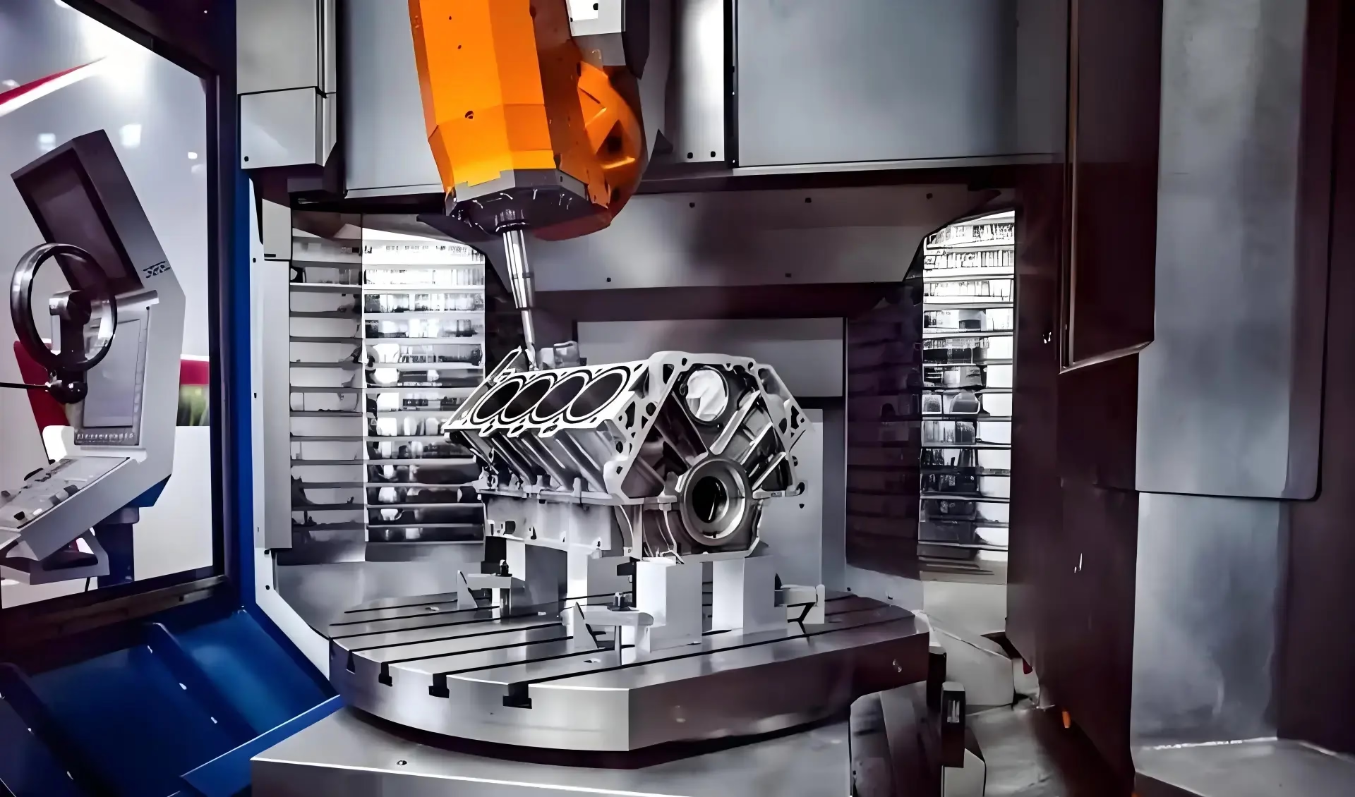
A five-axis machining center rotates the tool or the table instead. With a Ø 400 mm rotary table and simultaneous motion on two rotary axes, the cutter can approach the part from almost any direction in a single clamp. That removes the re-datuming error and keeps the relationship between features tight.
This is why some shapes are only practical on five-axis equipment. Impellers, turbine blades, angled ports and sculpted surfaces need the tool to tilt continuously as it follows the surface. A three-axis machine can only reach them by hand-fettling or by splitting the part into pieces that are later joined.
The trade-off is not free. Five-axis toolpaths are longer to program, the machine is slower to set up for simple work, and fixture design has to account for the table moving under the part. For a flat bracket with holes on one face, a three-axis machine is faster and cheaper. Use the right machine for the shape in front of you.
- 1One setup means one datumFewer re-fixturings keep feature-to-feature relationships tight.
- 2Simultaneous axes reach sculpted surfacesThe tool tilts continuously instead of stepping around the part.
- 3Simple parts do not need five axesPrismatic work on one or two faces runs cheaper on three-axis mills.
Tolerance, surface finish and where the cost sits
Tolerance and finish are two separate conversations, and mixing them causes trouble. A part can be dimensionally tight and still have a rough surface, or smooth and loose. Tolerance controls where the surface sits in space. Finish controls how smooth that surface is.
Our standard machining tolerance is ±0.005 mm (±0.0002 in). That is achievable on features with good tool access, rigid fixturing and stable material. It is not achievable on a 0.8 mm thin wall that flexes under clamping pressure, or at the bottom of a deep pocket where the cutter is unsupported.
Surface finish follows the same logic. As-machined parts run Ra 1.6–3.2 μm. A high-quality machined finish lands at Ra 0.8–1.6 μm with a controlled stepover and sharp tooling. Fine finishes at Ra 0.2–0.8 μm usually need a finishing pass with a small stepover, or a secondary operation such as lapping or polishing.
The practical rule is to specify the loosest tolerance and the roughest finish that still makes the part work. Tightening a tolerance from ±0.05 mm to ±0.005 mm across a whole drawing does not make the assembly better. It makes the part slower to cut, harder to inspect and more likely to be rejected at final inspection for a dimension that never mattered.
- 1Tighten only functional dimensionsBearing seats, mating bores, seal grooves and datum faces.
- 2Leave cosmetic faces looseNon-mating outer surfaces rarely need better than ±0.1 mm.
- 3Thin walls fight the toleranceBelow about 1 mm, clamping and cutting forces dominate the result.
Material choice and how it behaves at the cutter
Material selection is not only about strength. It decides how the part cuts, how it finishes and how stable it stays after machining. Aluminium 6061-T6 is the default for prototypes and fixtures because it machines fast, holds tolerance well and takes anodizing cleanly. 7075 offers higher strength but is gummier and harder on tooling.
Stainless grades 303 and 304 machine very differently. The 303 free-machining grade breaks chips cleanly and holds a good finish. The 304 grade work-hardens under a dull cutter, so the tool has to stay sharp and the feed rate has to stay high enough to cut rather than rub. 17-4PH gives high strength after heat treatment but needs more care on the finishing pass.
Titanium TC4 (Ti-6Al-4V) and Inconel sit at the difficult end. Both generate heat at the cutting edge rather than carrying it away in the chip, so tool life drops sharply and cutting speeds fall. They are still machinable, but the toolpath has to be planned around heat, not around cycle time.
Plastics behave on their own terms. POM and PEEK hold tolerance well and are stable. ABS and PP move with temperature and clamp pressure, so a tolerance that works on aluminium may not hold on a soft polymer. If the part has to be dimensionally tight, the material choice is part of that decision.
- 1Aluminium 6061-T6Fast to cut, stable, good anodizing base for most prototypes.
- 2Stainless 303 vs 304303 machines freely; 304 work-hardens if feed rates drop.
- 3Titanium and InconelHeat stays at the edge; slower speeds and shorter tool life.
Five design checks before you release a drawing
Check tool access first. Look at every pocket and slot and ask what diameter cutter can reach the bottom. A pocket narrower than about four times the cutter diameter, and deeper than about three times the cutter diameter, will need a smaller tool and a slower pass. If the corner radius is smaller than the standard radius for that depth, the shop has to switch tools mid-operation.
Check wall thickness next. Walls under about 1 mm in aluminium, or under about 1.5 mm in stainless, tend to move during machining. They also move during anodizing or heat treatment. If a thin wall carries a tight tolerance, expect the shop to leave material and take a light finishing pass, which adds time.
Check the datum scheme. Pick three faces or features that a machinist can actually clamp and probe, and reference the drawing to those. A drawing dimensioned from a curved surface or from a feature that is cut late in the process forces the shop to guess, and guessing costs tolerance.
Finally, check the thread and hole callouts. Specify standard thread pitches, standard drill sizes and standard corner radii. Every non-standard callout means a special tool or a manual operation, and those are the steps most likely to introduce variation.
- 1Tool accessConfirm a cutter can reach the bottom of every pocket.
- 2Wall thicknessKeep thin walls above 1 mm where tolerance matters.
- 3Datum schemeReference to faces a machinist can clamp and probe.
Which process fits which part
Match the geometry to the machine before you ask for a quote.
| Part characteristic | Best fit | Why it fits | Watch out for |
|---|---|---|---|
| Flat plate, holes on one face | 3-axis milling | Single setup, short cycle | No advantage in five axes |
| Features on four or five faces | 4-axis or 5-axis | One clamp, one datum | Fixture must clear the table |
| Sculpted or angled surfaces | 5-axis simultaneous | Tool tilts along the surface | Longer programming time |
| Round shaft with cross-holes | Mill-turn center | Turning and milling in one setup | Bar stock size limits |
| Thin wall under 1 mm | Any, with light passes | Spring passes control movement | Tolerance may still drift |
| Titanium or Inconel part | 5-axis, rigid setup | Fewer setups limit heat cycles | Short tool life, slower speeds |
| Prototype, one to ten parts | 3-axis or 5-axis | No tooling cost, fast turnaround | Hand finishing may be needed |
The verdict: match the machine to the shape
If the part has features on one or two faces and loose tolerances, specify three-axis milling and keep the cost down. If it has features on five faces, sculpted surfaces or a tight feature-to-feature relationship, specify five-axis and accept the higher setup cost. Choosing the wrong one adds setups or adds cycle time, and neither is recoverable later.
Questions engineers ask before releasing a drawing
What is the difference between three-axis and five-axis machining?
A three-axis machine moves the tool linearly in X, Y and Z. A five-axis machine adds two rotary axes, so the tool or the table can tilt as it cuts.
That extra motion means the cutter can reach angled and sculpted surfaces in one setup instead of several. It also keeps the part in one clamp, so feature-to-feature relationships stay tighter.
How tight a tolerance can a CNC processing product hold?
Our standard is ±0.005 mm (±0.0002 in) on features with good tool access and rigid fixturing.
Thin walls, deep pockets and soft materials reduce what is realistic. On those features, a looser tolerance and a light finishing pass usually give a better result than a tight number that cannot be inspected reliably.
Which surface finishes are available?
As-machined parts run Ra 1.6–3.2 μm. A high-quality machined finish is Ra 0.8–1.6 μm, and fine finishes reach Ra 0.2–0.8 μm.
Secondary operations include anodizing, plating, powder coating, black oxide, bead blasting, polishing and laser marking. Laser marking holds a minimum character height of 1.5 mm.
Do I need a minimum order quantity?
No. We run from a single prototype up to 10,000+ part runs.
Small runs are quoted on the same setup logic as large ones, so the design checks on this page matter just as much for one part as for a production batch.
How long does a quote take, and when can production start?
Quotation and a free DFM analysis come back within 12 hours.
Production can start within 24 hours of approval, and parts typically ship in 3–5 days. Historical late-delivery probability is below 2%.
How is my design kept confidential?
Uploads are secure and confidential. We can sign an NDA on request before you send drawings.
Every part is inspected 100% before shipment, with raw material checks, in-process monitoring and final inspection. Reports are available on request.
Send a drawing and get a manufacturability read
Upload your CAD file and we will return a quote plus a free DFM analysis within 12 hours, including any feature that will drive cost or tolerance risk.
12-hour quote100% inspectionNo minimum orderNDA on request
More from the shop floor
We publish setup notes, tooling trials and inspection data from the factory floor.











