
EV CHAdeMO Adapter Mounts Machining
A CHAdeMO adapter mount is a stationary bracket that holds the adapter housing in a vehicle or on a charging post. This page explains what drives the geometry, where the tolerance budget goes, and which parts should not be machined this way.
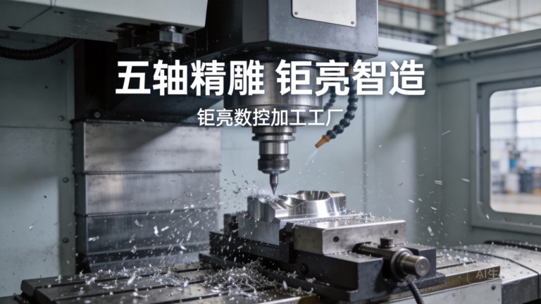
What an adapter mount actually has to do
The mount is not a panel. It carries the weight of the adapter housing plus the insertion and withdrawal loads a driver applies at the connector, and it holds the mating face at a fixed angle so the latch can engage. On a vehicle retrofit it also has to sit inside an existing cavity, which is where the 3D contour comes from.
Three interfaces set the drawing. The bolt pattern to the chassis or post, the pilot bore or dowel pair that locates the adapter housing, and the mating face plane that sets insertion angle. Everything else is clearance. If the pilot bores drift, the connector does not seat squarely and the latch load rises.
CHAdeMO remains in service in Japan, Europe and North America, and dual-standard vehicles and retrofit kits still need these brackets. That keeps demand low-volume and mixed, which favors machining over die casting for anything under a few thousand pieces.
So EV CHAdeMO adapter mounts machining is mostly a locating problem. Cut the pilot features true to the mounting face, hold flatness, and keep the wall thickness even enough that the bracket does not move when the bolts are torqued.
- 1Locating featuresPilot bore or dowel pair controls connector alignment
- 2Mounting faceFlatness sets insertion angle and latch load
- 3Wall thicknessEven section keeps torque from springing the bracket
Where the tolerance budget goes
A typical drawing asks for dowel-hole position within 0.02 mm and flatness under 0.02 mm on the mating face. That is not a single-number requirement, it is a stack. Position error eats the clearance between the adapter housing and its locating pins, and flatness error tilts the mating face, which changes insertion angle across the width of the connector.
To hold that repeatably you need the locating features cut in the same setup as the mounting face, or in a setup whose relationship is proven. On a 3-axis machine that means fixturing twice and trusting the fixture. On a 5-axis machine the part can be turned and the second face cut without losing the datum, which is why bracket geometry with angled pads tends to go to simultaneous 5-axis work.
Thermal drift matters more than most drawings admit. Aluminium moves roughly 23 μm per meter per °C. A 300 mm bracket that warms 5 °C between roughing and finishing shifts about 35 μm, which is larger than the position callout. Rough, let it cool, then finish.
Our floor holds ±0.005 mm on critical features when the process is set up for it, but not every feature on a mount needs that. Put the tight tolerance on the pilot and the mating face, and open up everything that only passes a bolt. Tightening clearance holes buys nothing and adds cost.
- 1Same-setup rulePilot bore and mating face from one datum
- 2Thermal stepRough, cool, then finish on thick sections
- 3Selective toleranceTight on pilots, open on clearance holes
Material choice and what it does to the cut
Most mounts we see are 6061-T6 or 6082. Both machine cleanly, take anodizing well, and give a good stiffness-to-weight ratio. 6082 is common with European customers because it is widely stocked there. If the bracket is a structural member of the post rather than a housing carrier, 7075 gives higher strength but cuts slower and is less forgiving of thin walls.
For higher durability or where the bracket sees road spray and salt, 316L stainless is the usual pick. It work-hardens, so keep radial engagement low and feed steady. Do not dwell. 17-4PH in the H900 condition is the middle path when you want stainless corrosion behavior with better strength than 304.
Where EMI shielding or grounding is specified, the mount may be aluminium with a conductive anodize, or copper and brass inserts pressed in. Beryllium copper and C36000 brass both machine well at small feature sizes. Conductive anodize is a coating choice, not a material choice, and it changes how you mask the pilot bores.
Plastics show up in prototype housings and covers rather than load-bearing mounts. POM and PEEK hold thread forms better than ABS or PP, but none of them replace a metal bracket in a load path.
- 1Aluminium6061-T6, 6082, 7075 for stiffness at low mass
- 2Stainless316L or 17-4PH for salt spray and durability
- 3Grounding partsConductive anodize or pressed brass inserts
Features that need EDM or mill-turn work
Not every mount is a plate with holes. Some carry a cooling channel for the adapter's power electronics, a snap-fit lip for the housing cover, or a threaded insert pattern that has to sit on a curved surface. Those features change the process plan.
Internal cooling channels with small cross sections are usually cut by sinker EDM after the main form is milled, or the part is split and bonded. Wire EDM handles sharp internal corners and thin webs where a cutter would deflect. It also gives a square corner without a corner radius, which matters when a seal has to sit flat.
Threaded inserts and small tapped holes on angled faces are a mill-turn job. A mill-turn center turns the body and mills the angled pads in one cycle, so the thread axis and the bore axis stay related. Moving the part to a second machine adds a setup error for no gain.
Surface finish follows function. Mating faces and pilot bores are usually held to Ra 0.8–1.6 μm so a seal or a locating pin seats predictably. Non-critical outer surfaces can run Ra 1.6–3.2 μm as machined. Where a sliding or sealing surface exists, Ra 0.2–0.8 μm is achievable, but it is a separate operation and should be called out only where it is needed.
- 1Sinker EDMSmall internal cooling channels after milling
- 2Wire EDMSharp corners and thin webs, no cutter radius
- 3Mill-turnThreads and bores on angled faces in one cycle
Inspection and the limits of the process
A mount that measures good on a bench can still fail in the field if the datum used for inspection is not the datum used for machining. We cut and inspect from the same reference where possible, and report position on the pilot features rather than on an edge. CMM reports are available on request.
The dimensional check is only part of it. Coating thickness on anodized or plated parts changes the fit of a pressed insert, so either mask the bore or allow for the build. Laser marking needs a minimum character height of 1.5 mm to stay legible after coating.
Now the boundary. Machining is a poor fit when the part is a thin stamped cover with no critical locating features, when annual volume is high enough to justify a die, or when the geometry is a deep, thin-walled shell that would need to be split anyway. In those cases the right answer is sheet metal fabrication, die casting or vacuum casting, and we will say so.
Machining is the right answer when the pilot features are tight, the volume is low or mixed, the design is still moving, or a prototype is needed before tooling is committed. Our floor runs from one prototype to 10,000+ part runs with no minimum order quantity.
- 1Datum disciplineCut and inspect from the same reference
- 2Coating buildMask bores or allow for plating thickness
- 3Wrong processThin covers and high volumes belong elsewhere
Which process fits which mount feature
Match the feature to the machine before quoting.
| Feature | Usual process | Why |
|---|---|---|
| Pilot bore + mating face | 5-axis, one setup | Keeps position and flatness related |
| Angled mounting pads | 5-axis or mill-turn | Avoids a second fixture and its error |
| Small internal channel | Sinker EDM | Cutter cannot reach the cross section |
| Sharp internal corner | Wire EDM | No corner radius left by a tool |
| Threaded inserts | Mill-turn | Thread axis tied to the bore axis |
| Sealing face, Ra 0.8-1.6 μm | Fine finish pass | Seal seats predictably |
| Cover with pull-out lip | 3-axis + insert | Snap features do not need 5-axis |
| Prototype bracket | 3-axis, soft jaws | Fastest path when contours are simple |
When to machine, when to tool up
If the mount carries tight pilot features, low or mixed volume, or an unproven design, machine it. If it is a thin cover with no locating features, or a stable design at high annual volume, go to sheet metal or die casting instead.
Questions engineers ask before quoting
How tight does the pilot bore really need to be?
Tighter than the clearance between the adapter housing pins and their holes, with margin for coating. On most drawings that lands near 0.02 mm position on the dowel pair, and the mating face flatness follows it.
Going below that is possible on our floor, but check whether the mating housing is made to the same class. A tight bore against a loose housing does not improve alignment.
Does anodizing change the fit?
Yes. Anodic coatings grow into and out of the surface, and hardcoat is thicker than a clear decorative coat. If a bore or a press fit is called out, either mask it before coating or leave stock and cut after.
Tell us the coating and thickness at quote time so the allowance is in the model rather than in a rework loop.
What finish should I specify on a sealing face?
Ra 0.8–1.6 μm is the usual range for a face that a gasket or seal sits on. It is achievable with a fine finish pass on the same setup as the bore.
Only call out Ra 0.2–0.8 μm where a sliding or dynamic seal actually runs. It adds a separate operation and cost.
Can you mill a cooling channel into the mount?
Small internal channels usually go to sinker EDM after the outer form is milled, or the part is split and reassembled. Whether that is cheaper than an external channel depends on the cross section and how deep it runs.
Send the section and we will tell you which route holds the tolerance.
How do you handle a mixed bracket family?
Common mounting faces with different arm lengths or angles are a good fit for 5-axis work with a single fixture. Datum stays the same across the family, so position does not drift between variants.
There is no minimum order quantity, so a family can start as one piece per variant.
What do you need to quote a mount?
A 3D model or a 2D drawing with the critical callouts marked, the material and finish, and the quantity. If the model exists but the drawing does not, we will run a free DFM analysis and flag what is missing.
Uploads are confidential and an NDA is available on request. Quote and DFM analysis come back within 12 hours, and production can start within 24 hours of approval.
Send the mount drawing and get a process plan
Upload a model or drawing and we will return a quote with a free DFM analysis, the recommended process route, and the critical callouts we would tighten or open.
12-hour quote100% inspectionNo minimum order quantity
More from the shop floor
We publish setup notes, tooling trials and inspection data from the factory floor.











