
EV Knock Sensor Mounts CNC Turning: How Geometry Drives Signal Clarity
A knock sensor mount is a mechanical filter. Whatever the machined seat does to vibration, the sensor reports as combustion data. This page explains how EV knock sensor mounts CNC turning holds seat geometry, which materials behave, and when turning is the wrong process for the part.
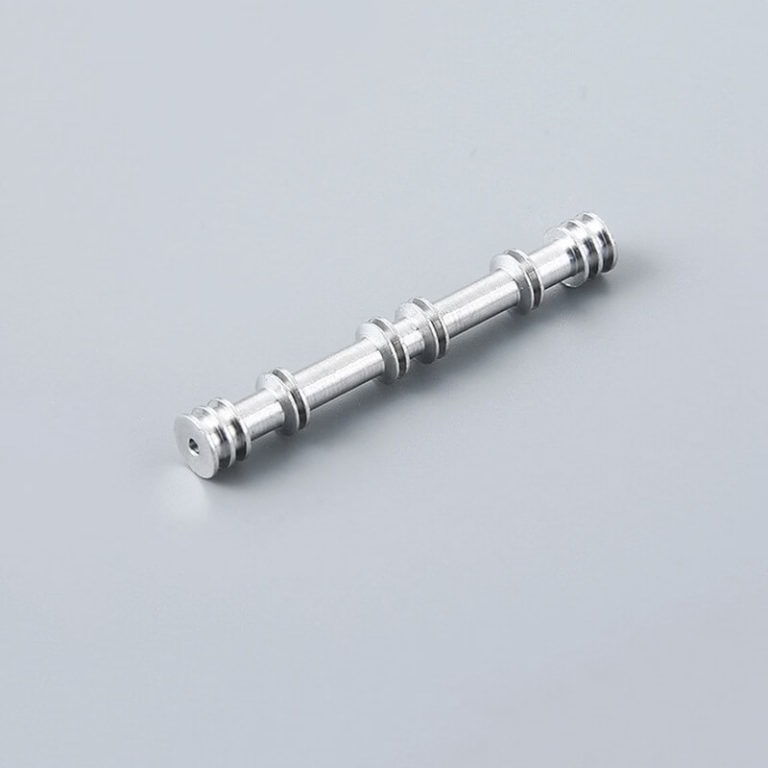
Why the Mount Shapes the Knock Signal
A knock sensor is a piezoelectric accelerometer bolted to the block or cylinder head. It converts structure-borne vibration into a charge signal. The mount is the only path that energy can take, so its stiffness and contact area decide what reaches the crystal. On an EV range extender or a hybrid engine, the same mount also sits near inverter and motor harmonics that were never present in a pure combustion powertrain.
That changes the job. The sensor must still hear a 5–15 kHz ring from detonation, but it now sits in a noisier mechanical environment. A seat that is slightly convex, or a bolt face that is not square to the thread axis, creates a micro-gap. The gap opens and closes under load. Each cycle adds a small impulsive event that the ECU can read as knock.
This is why EV knock sensor mounts CNC turning is specified rather than a bracket cut on a mill. Turning holds a single axis of rotation and keeps the seating face, pilot bore and thread concentric in one setup. Concentricity translates directly into a uniform clamping load around the sensor flange.
The effect is measurable in the frequency domain. A well-seated sensor shows a clean resonance peak. A poorly seated one shows a broader, lower peak with sidebands. The ECU calibration then has to raise its detection threshold, and real knock events get missed.
Five Dimensions That Decide Detection Quality
Most knock sensor failures traced back to the mount come from four or five features, not from the sensor body. Each one has a physical reason behind its tolerance. Tightening a dimension that does not matter adds cost without adding signal quality.
Seat flatness controls contact. A seat that is flat within 0.01 mm across the sensor footprint gives near-full contact. Beyond that, contact area drops fast and the joint behaves like a spring rather than a rigid connection.
Bore-to-thread concentricity controls clamping symmetry. If the pilot bore and the thread axis drift apart, the sensor flange is loaded on one side. The crystal sees a bending moment instead of pure compression, which shifts its sensitivity.
Seat surface finish controls the interface. A turned face at Ra 0.8–1.6 μm is usually enough when a hardened washer is used. For direct metal-to-metal seating, Ra 0.2–0.8 μm removes the turning feed marks that act as tiny pressure ridges.
Thread pitch diameter and perpendicularity matter more than most drawings show. A thread that is not square to the seat tilts the sensor as it is torqued. Two degrees of tilt can move the sensing axis off the intended direction.
- 1Seat flatness0.01 mm across the sensor footprint keeps contact uniform.
- 2ConcentricityBore and thread on one axis so clamping load stays symmetric.
- 3Surface finishRa 0.2–0.8 μm for direct seating, Ra 0.8–1.6 μm with a washer.
- 4PerpendicularityThread square to seat within 0.02 mm to stop sensor tilt.
Material Choice Changes Machining Strategy
The mount has to match the thermal expansion of whatever it bolts to. Aluminum mounts on an aluminum housing expand together, so preload stays stable across temperature. A steel mount on an aluminum housing grows apart, and preload can fall by 30% or more at operating temperature.
Aluminum 6061-T6 is the default for prototype and low-volume EV mounts. It turns cleanly, holds Ra 0.8 μm without polishing, and takes hardcoat anodizing when the seat needs wear resistance. It is also light, which matters when the mount sits on a cantilevered bracket.
Where stiffness matters more than weight, 7075-T6 gives roughly twice the yield strength of 6061. It machines well but is less weldable and more prone to stress corrosion if anodized incorrectly. Use it when the mount is also a structural member.
Stainless 303 or 17-4PH appears when corrosion resistance is the driver, such as mounts exposed to road salt or coolant. 303 turns easily but is non-magnetic only in the annealed condition. 17-4PH holds strength after aging and is the better choice for a high-vibration joint.
Beryllium copper and brass mounts are uncommon but appear in some sensor housings where electrical shielding is part of the function. They turn well and hold fine finishes, though tool wear and chip control need attention.
When Turning Is the Wrong Process
Turning is a single-point process on a rotating workpiece. It is excellent for round, concentric features and poor for anything that is not rotationally symmetric. A mount with a rectangular flange and two offset bolt holes is not a turning part unless the flange is small enough to be milled in a second operation.
The practical rule is simple. If more than about 60% of the critical features are on one axis of rotation, turning is the economical choice. If the part is mostly a flat plate with bosses, milling or a mill-turn center wins.
Wall thickness sets another boundary. Very thin-walled sleeves chatter under turning forces. Below roughly 1.5 mm wall on aluminum, or 2 mm on stainless, we move to a mill-turn setup or add a supporting mandrel. Chatter marks on a sensor seat are a direct signal-quality problem.
Deep, small-diameter bores are also a poor fit for standard turning. A bore depth over 4× diameter needs a boring bar that deflects, and the resulting taper shows up as a non-uniform seat. Gun drilling or a dedicated boring operation is the better route.
Finally, thread-to-seat perpendicularity is easier to hold when the part can be finished in one chucking. If the drawing forces a flip between operations, expect to add an in-process check or a dedicated fixture.
How We Hold the Seat on a Turned Mount
- 1Start from bar stock on the same heatOne lot number per run. Aluminum 6061-T6 or 17-4PH, cut to length with 3 mm facing allowance.
- 2Face and turn the seat in the first chuckingRough at 0.3 mm depth, finish at 0.1 mm. Target Ra 0.8–1.6 μm with a 0.4 mm nose radius insert.
- 3Bore the pilot and cut the thread in the same setupConcentricity within 0.01 mm TIR. Thread depth checked with a go/no-go gauge every 20 parts.
- 4Part off and finish the back face on a second opSoft jaws machined to the finished diameter. Back face parallel to the seat within 0.02 mm.
- 5Deburr the seat edge by hand, never by tumblingTumbling rounds the seat edge and changes the contact footprint. Hand deburr or use an orbital tool.
- 6Inspect flatness, Ra and perpendicularity before packingFlatness on a granite plate, Ra with a portable profilometer, perpendicularity on a CMM.
Turning vs Milling vs Mill-Turn for Sensor Mounts
Use this as a first filter when the drawing lands on your desk.
| Part feature | CNC turning | CNC milling | Mill-turn |
|---|---|---|---|
| Round seat and pilot bore | Best fit, one setup | Needs a boring head | Good fit |
| Rectangular flange with offset holes | Second op required | Best fit | Good fit |
| Concentricity under 0.01 mm | Holds in one chucking | Harder to hold | Holds well |
| Wall under 1.5 mm (aluminum) | Chatter risk | Better support | Best control |
| Deep bore over 4× Ø | Bar deflection | Limited reach | Best option |
| Thread square to seat | Single setup | Fixture dependent | Single setup |
The Takeaway
If your mount is round with a concentric seat, turning in one chucking is the right call and the cheapest way to hold signal quality. If it is a flat plate with offset bosses, stop trying to turn it and send it to a mill-turn center.
Questions Engineers Ask Before Releasing the Drawing
What surface finish does a knock sensor seat actually need?
With a hardened washer between the sensor and the seat, Ra 0.8–1.6 μm is enough. The washer bridges the feed marks.
For direct metal-to-metal seating, go to Ra 0.2–0.8 μm. Turning feed marks act as pressure ridges and reduce real contact area.
Can anodizing change the seat tolerance?
Yes. Type II anodizing adds roughly 5–15 μm per surface, and hardcoat adds more. A 20 μm build on a bore changes the fit.
Mask the seat and the pilot bore, or cut the pre-anodize dimension undersize. We mark masked zones on the traveler so the finisher does not guess.
How do I know the mount, not the sensor, is causing false knock?
Compare the frequency spectrum against a known-good build. A mount problem broadens the resonance peak and adds sidebands.
A quick check: torque the sensor to spec, then re-run. If the peak shifts with torque, the seat or thread is the variable.
Do you need the full engine assembly to quote a mount?
No. A 2D drawing with tolerances, material and finish is enough for a quote and a DFM review within 12 hours.
If the seat tolerance is not on the drawing, tell us the sensor model and we will suggest a starting range.
What is the smallest and largest mount you can turn?
The compact lathes cover parts down to a few millimeters in diameter. The largest turning envelope is 4,000 mm in length.
For a sensor mount, the practical range is a Ø10–80 mm body. Larger flanges usually move to mill-turn.
Send the Drawing, Get a DFM Review
Upload your mount drawing and we will return a quote with a free DFM analysis within 12 hours. No minimum order quantity, from one prototype to 10,000+ parts.
12-hour quoteNo MOQNDA on request
More from GreatLight
We publish setup notes, tooling trials and inspection data from the factory floor.











