
01
Is your shaft oval, not round?
A part that should be round comes back with 0.03 mm lobing. It happens when a thin-wall tube is gripped too hard or the chuck pressure is never adjusted. Assembly then binds and you scrap the lot.
Turned parts cut from bar stock on lathes and mill-turn centers. Diameters to Ø813 mm, lengths to 1,575 mm, held to ±0.005 mm. Send a drawing or STEP file; you get a quote and a DFM review within 12 hours.
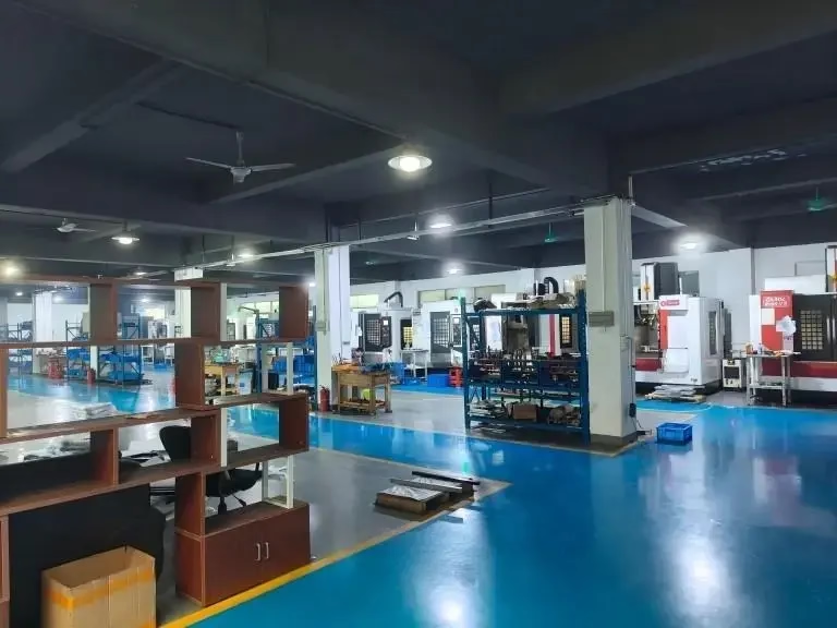
These are the failures we see on incoming drawings every week.
A part that should be round comes back with 0.03 mm lobing. It happens when a thin-wall tube is gripped too hard or the chuck pressure is never adjusted. Assembly then binds and you scrap the lot.
The pitch diameter drifts mid-run and the mating nut only goes halfway. On a turned part this usually means tool wear was not tracked or the thread was single-pointed without a gauge check. Rework means re-chasing every piece.
The bore sits 0.05 mm off the outside diameter. If the part is flipped between two chuckings without a soft jaw or a sub-spindle, that offset is baked in. Bearings press in crooked and the shaft runs hot.
A turned surface at Ra 3.2 μm will not hold an O-ring. Too many shops ship as-machined and call it done. If the drawing calls Ra 0.8 μm or finer, the feed rate and insert nose radius have to be set for it.
Bar stock in, gauge-checked parts out, with the process fixed before the first chip.

Roundness on a turned part is a workholding problem before it is a cutting problem. Thin-wall tubes and long slender shafts deflect under chuck pressure, so we cut soft jaws to the actual bar diameter and set grip force per job rather than per machine. On parts with a length-to-diameter ratio past 4:1 we bring in a tailstock or a steady rest.
For milled features on a turned part, 16 mill-turn centers let us drill, cross-hole and slot in the same setup. One chucking means the bolt circle stays concentric with the bore, and you avoid the second-op fixture that adds error.
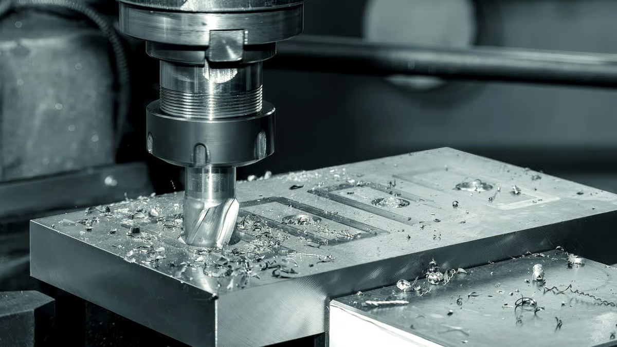
Holding ±0.005 mm across a production run means controlling temperature, tool wear and spindle growth. We rough and finish in separate passes, let the part stabilize, then take the finish cut. In-process gauging flags drift before the feature leaves tolerance, not after.
GD&T callouts are read off your drawing and checked with the method they imply: concentricity on a bench center, position on a CMM, surface finish with a profilometer. Inspection reports come with the shipment when you ask for them.
Use this to decide before you send the file.
| Part shape | Better process | Why |
|---|---|---|
| Cylindrical, axial features | CNC turning | One chucking holds concentricity |
| Prismatic, flat pockets | CNC milling | Turning cannot reach the corners |
| Turned OD plus side holes | Mill-turn | Both features in one setup |
| Thin-wall tube under 1 mm | Turning with soft jaws | Chuck pressure must be controlled |
| Deep bore over 5× diameter | Turning plus boring bar | Standard tooling will chatter |
| Threads, grooves, knurls | CNC turning | Single-point and form tools cover it |
| Fine detail under Ø0.5 mm | Consider EDM | Cutting forces bend small features |
One shop for the turned part and the operations around it.
Bar-fed and chucked work on lathes and mill-turn centers. Shafts, bushings, fittings, spacers, threaded studs and valve bodies, from one piece to 10,000+.
Cross holes, flats and slots cut in the same setup as the turning. Keeps the bolt circle true to the bore on hydraulic and pneumatic fittings.
16 simultaneous 5-axis centers for contoured turned parts and features that a 3-axis setup cannot reach at the right angle.
Turned prototypes for fit and function checks before tooling. Same inspection routine as production, so the numbers carry over.
Anodizing, plating, black oxide, bead blasting and polishing. Laser marking down to 1.5 mm character height for traceability.
Pressed-in bearings, O-rings and sub-assembly, plus CMM reports and material certificates on request.
Numbers we build to, not marketing ranges.
| Item | Range | Note |
|---|---|---|
| Max turned diameter | Ø813 mm | Larger diameters on request |
| Max turned length | 1,575 mm | Steady rest for long shafts |
| General tolerance | ±0.005 mm | ISO 2768 unless stated |
| As-machined finish | Ra 1.6–3.2 μm | Standard turned surface |
| Fine finish | Ra 0.2–0.8 μm | On request, adds a pass |
| Threads | Any standard size | Custom threads need review |
| Minimum order | 1 piece | Prototype to 10,000+ runs |
| Quotation | Within 12 hours | Includes free DFM analysis |
Data points, not adjectives.
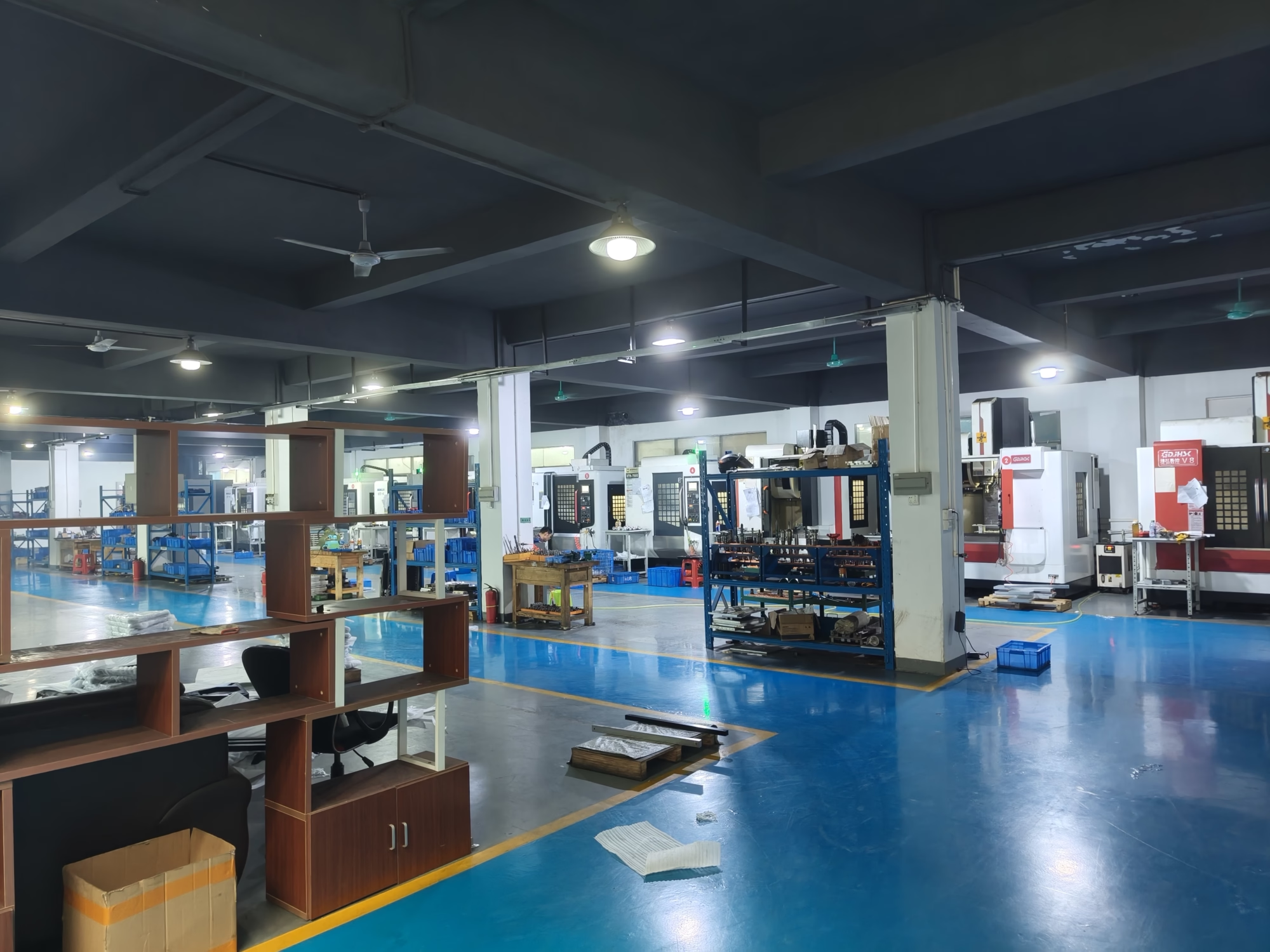
Fifteen years on turned parts, three wholly-owned plants and 7,600 m² of manufacturing space in Dongguan and Singapore.
Held on metals per ISO 2768 unless your drawing calls tighter. GD&T callouts checked with the method they imply.
16 simultaneous 5-axis centers, 16 mill-turn centers and 12 four-axis mills. Capacity for both one-offs and long runs.
Quotation and free DFM analysis back within 12 hours. Production can start within 24 hours of approval.
100% inspection before shipment, with raw material check, in-process monitoring and final inspection.
ISO 9001:2015, IATF 16949:2016, ISO 13485:2016 and ISO 27001:2022. NDA available on request.
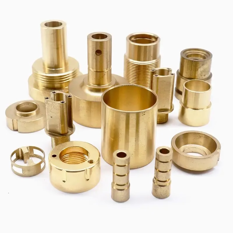
Copper and brass contacts, pins and heat-spreader parts turned to tight diameter control.
Bushings, sensor housings and motor shafts run under IATF 16949 process control.

Stainless turned components with burr-free bores and clean surface finishes.

Rollers, spacers and fittings up to 1,575 mm long, held concentric to the bore.
A CNC lathe turns a part against a single spindle with axial tools. A turning center adds a turret with live tooling, a sub-spindle and often a Y axis, so milling, drilling and back-side work happen in the same cycle.
For a simple shaft with a thread, a lathe is enough. If the part needs cross holes or a milled flat, a turning center removes the second operation and the error that comes with it.
Bar stock or a blank is gripped in a chuck or collet and spun. A single-point tool moves along the Z and X axes to face, turn, bore and thread the profile the program describes.
Tool offsets set the cutting edge position, so the machine compensates for wear and inserts without touching the program. That is why a turned diameter can be corrected mid-run.
±0.005 mm on metals per ISO 2768, tighter where the drawing calls it out and the geometry allows. Length, diameter and position are checked separately.
Very thin walls, long slender shafts and soft plastics will move more. Send the drawing and we will tell you which dimensions are realistic before you commit.
Aluminum 6061-T6, 2024, 7075 and 6082; stainless 303, 304, 316L, 17-4PH and 440C; steel 1018, 1045, 4140 and 4340; copper C101 and C110; brass C36000; titanium TC4; and plastics like POM, PEEK and PA.
Free-machining grades such as 303 stainless and C36000 brass cut cleanly and hold tight diameters. Titanium and Inconel need slower speeds and more tool changes.
Any standard thread size, cut with single-point tooling or a die head. Custom thread forms require a manual quote review because the tooling may need to be made.
Knurling depends on the material and the wall thickness. On thin-wall parts knurling can distort the bore, so we may suggest a cut knurl or a rolled feature instead.
As-machined turning lands around Ra 1.6–3.2 μm. A seal or bearing seat usually needs Ra 0.8–1.6 μm, and sliding or optical surfaces need Ra 0.2–0.8 μm.
Finer finish costs an extra pass and sometimes a different insert. Specify the finish where it matters instead of calling the whole part fine.
No minimum. We run one prototype and we run 10,000+ piece orders on the same machines and inspection routine.
Small quantities are quoted individually since setup time dominates the cost. Larger runs get bar feeders and unattended cycles.
Quote and free DFM analysis within 12 hours. Production can start within 24 hours of approval, and parts ship in 3–5 days.
That window assumes the drawing is released and the material is in stock. Exotic alloys and custom threads add a step because they need manual review.
Upload your CAD file and we will come back with a quotation, a DFM review and any tolerance we think should change.
12-hour quote100% inspectionNo minimum orderNDA on request
Trusted by engineers and manufacturers worldwide










Upload your 3D model or 2D drawing and get a quotation with a free DFM analysis. Maximum processing size 4,000 mm.
CNC Metals 13 grades
CNC Plastics 10 grades
Machines & processes 12 options
Surface & post-processing 10 options
Material: not selected Machine: not selected Post-process: not selected
Fill in this short form and we'll open WhatsApp with your message ready to send. We only use these details to reply to you.
Nothing is sent until you press send inside WhatsApp.