
Fast Rapid Prototyping Manufacturing: 7 Checks Before You Order
This guide explains what fast rapid prototyping manufacturing actually delivers, where each process hits its limit, and which questions decide whether a prototype matches your design intent. Written for design engineers and sourcing leads who need functional parts, not display models.
In this article
- 1
- 2
- 3
- 4
- 5
- 6
- 7
- 8
- 9
Key takeaways
What fast rapid prototyping manufacturing means in practice
Fast rapid prototyping manufacturing covers the window between a finished CAD model and a part you can bolt onto a test rig. It is not a single process. It is a set of decisions about stock, tooling, machine setup and inspection that decide how many days pass before a physical part reaches your bench.
The output that matters is a production-representative part. Same alloy, same wall thickness, same fastener threads, same surface condition. A concept model that looks right but behaves differently under load will send your test program in the wrong direction.
Speed comes from removing non-value steps. No hard tooling, no mold lead time, no minimum batch. A machined or printed part starts from a digital file and a material block. When the shop has the stock on the shelf and a machine slot open, the first article can be cut the next working day.
This guide is for engineers specifying prototypes in metal or engineering plastics, and for buyers comparing suppliers on something other than price per piece.
Which process fits which prototype
Subtractive and additive methods solve different problems. CNC machining starts with a solid block and removes material. The result has wrought material properties, tapped holes that hold torque, and surfaces you can seal with an O-ring. It is the default when the part must survive a pressure test, a vibration sweep or a drop.
Additive manufacturing builds layer by layer. Metal powder bed fusion and resin processes let you produce internal channels, lattice structures and merged assemblies that no end mill can reach. The trade-off sits in anisotropy and surface texture. As-built surfaces land around Ra 10–15 μm on many metal platforms and need secondary machining on sealing faces.
Sheet metal and welded assemblies cover brackets, enclosures and chassis parts. Laser cutting and press brake forming reach ±0.1 mm on formed features across a 1,000 mm part, which is usually enough for fit checks and cable routing validation.
A mixed build often wins. Print the complex core, machine the sealing face and the bearing bore, then finish the assembly together. That combination keeps the schedule short without sacrificing the critical interfaces.
- 1CNC machiningFunctional testing, tight bores, threads, sealing faces, metal or engineering plastic.
- 2Metal 3D printingConformal cooling, internal channels, topology-optimized geometry.
- 3Resin printing and vacuum castingErgonomics models, translucent light pipes, small bridge batches.
- 4Sheet metalBrackets, panels, enclosures, weldments up to 4,000 mm.
Tolerance is a cost curve, not a single number
A drawing that says ±0.005 mm everywhere is not more precise than a drawing that says ±0.005 mm on the bore and ±0.1 mm on the outside profile. It is just more expensive. Every tight feature adds a roughing pass, a semi-finish pass, a temperature-stabilized finish pass and a CMM check.
The practical split falls into three bands. General machined features hold ±0.05 mm without special effort. Bores, spigots and mating faces reach ±0.005 mm on a 5-axis machine with the right fixturing. Non-critical clearance holes and cosmetic edges can sit at ±0.1 mm all day.
Thermal drift is the quiet enemy. A 100 mm aluminum part grows roughly 0.0023 mm per °C. If the shop floor swings 8 °C between the roughing cut and the finish cut, that alone eats the tolerance budget. Stable shops measure after the part has soaked, not straight off the spindle.
Thin walls behave differently again. Below about 0.8 mm in aluminum, cutting forces push the wall away from the tool and the finished dimension drifts. If your design needs a 0.5 mm wall, say so at quoting stage so the shop can plan support or a different process.
Surface finish and material choices that change the result
Finish callouts decide how the part feels and how it seals. As-machined surfaces sit at Ra 1.6–3.2 μm and are fine for brackets and internal structure. Sealing faces and bearing journals usually need Ra 0.8–1.6 μm. Optical and fluid-contact surfaces can reach Ra 0.2–0.8 μm with additional lapping or fine boring.
Coating adds material. Anodizing grows the surface by roughly half the oxide thickness per side, so a 20 μm coating moves a dimension by about 10 μm per face. Mask threads and bores, or cut them undersize before coating. Hardcoat anodizing on aluminum can add 25–50 μm and will close a fine thread if you ignore it.
Material selection for prototypes should mirror the production intent. Aluminum 6061-T6 is the workhorse for housings and brackets. 7075 gives higher strength for stressed fittings. 17-4PH stainless covers corrosion-resistant shafts and valves. PEEK and POM handle wear and chemical exposure where metal is not an option.
Do not prototype in a substitute alloy and expect the test data to transfer. Yield strength, thermal expansion and damping differ enough to change a resonance or a press-fit result.
Seven checks before you place the order
First, ask how the shop handles DFM. A supplier that returns a marked-up model within a day is reading your geometry, not just your quantity. Second, ask which machines will run the part. The answer tells you whether the tolerance you wrote is achievable or aspirational.
Third, ask about in-house finishing. Sending parts out for anodizing adds a week and a second shipping risk. Fourth, ask for the inspection plan. 100% inspection before shipment sounds good, but you want to know which dimensions get measured and with what instrument.
Fifth, check the quality system against your industry. ISO 9001:2015 covers general work. IATF 16949:2016 matters for automotive. ISO 13485:2016 applies to medical devices. ISO 27001:2022 covers information security if your files are sensitive.
Sixth, confirm the confidentiality route. An NDA before file transfer is standard practice for unreleased designs. Seventh, confirm capacity for the follow-on batch. A supplier that can move from one prototype to a 10,000-part run without requalifying the process saves a full validation cycle.
Why the cheapest quote often costs more
Price per part is a small part of the total. A prototype that arrives with a wrong bore, a cracked thin wall or a finish that peels costs a rework cycle, a schedule slip and sometimes a missed design review. Those hours rarely show up in the purchase order.
The cost drivers are setup count, material form and inspection depth. A part cut in one 5-axis setup is usually cheaper than the same part cut in four 3-axis setups, even at a higher hourly rate. Near-net stock reduces machining time but costs more per kilogram.
Late delivery is the expensive failure. If a supplier misses the date, the test rig sits idle and the whole program shifts. Asking for a realistic ship date beats asking for the fastest one.
A shop that gives you a 12-hour quote and a free DFM review is not being generous. It is removing the back-and-forth that usually eats the first two days of a project.
How a fast prototyping job runs, step by step
Typical sequence when the file is clean and the stock is in-house.
- 1Send the 3D file and the 2D drawingSTEP or native CAD plus a drawing with datum scheme, critical dimensions and finish callouts. Note which dimensions are functional.
- 2Read the DFM feedbackLook for tool reach limits, sharp internal corners, thread depth and wall thickness warnings. Fix them in CAD, not on the machine.
- 3Confirm material and stock formPlate, bar or block. Plate distorts less on thin parts; bar gives better grain direction on shafts.
- 4Approve the setup and fixture planAsk how many setups. Each extra setup adds a datum shift and a day. Five-axis work should reduce setups, not add them.
- 5Cut the first articleRough, stress-relieve if needed, semi-finish, then finish. Check the first part before the batch continues.
- 6Inspect and documentFirst-article report on the critical dimensions, material certificate, and a finish check with a profilometer or visual standard.
- 7Finish and shipAnodizing, plating, bead blasting or laser marking. Re-check threads and bores after coating.
Process selection at a glance
Use this when the test method, not the shape, decides the process.
| Process | Typical tolerance | Best for | Watch out for |
|---|---|---|---|
| 3-axis CNC | ±0.05 mm | Prismatic parts, plates, simple pockets | Undercuts need a second setup |
| 5-axis CNC | ±0.005 mm | Complex contours, angled holes, one-setup parts | Higher hourly rate, needs good CAD |
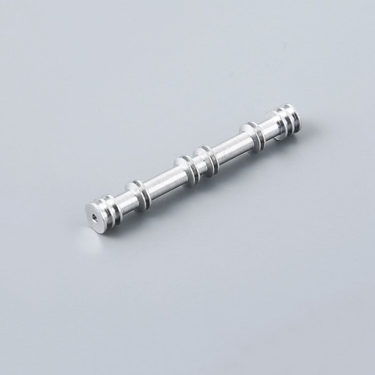
| CNC turning and mill-turn | ±0.01 mm | Shafts, bushings, threaded connectors | Long slender parts deflect |
| Metal powder bed fusion | ±0.1 mm | Internal channels, lattice, merged assemblies | Anisotropy, rough as-built surfaces |
| SLA and vacuum casting | ±0.2 mm | Ergonomics models, clear parts, bridge batches | Low heat resistance, UV ageing |
| Sheet metal | ±0.1 mm | Brackets, panels, enclosures | Bend radius and springback limits |
The short answer
If the part must carry load, seal, or fit a production assembly, machine it from the production alloy and pay for the tight features only where they matter. If the part only has to look and feel right, print or cast it and save the machining budget for the next revision.
Questions engineers ask before the first cut
How fast can a machined metal prototype ship?
With a clean STEP file and stock on the shelf, production can start within 24 hours of order confirmation and parts typically ship in 3–5 days.
Add time for outside finishing if the coating is not done in-house, and add a day if the part needs a first-article report.
Should I send a 3D model or a 2D drawing?
Send both. The model defines the geometry; the drawing defines the datums, the critical dimensions and the finish callouts.
If you only have a model, mark the functional dimensions in a note so the shop knows where to spend the tolerance budget.
Can you hold ±0.005 mm on every feature?
Not on every feature, and you would not want to pay for it. ±0.005 mm is achievable on bores, spigots and mating faces with the right fixturing and a stable shop floor.
General profiles and clearance holes are normally held at ±0.05 mm to ±0.1 mm.
How do I handle confidential designs?
Ask for an NDA before you upload the files. Uploads are kept secure and confidential, and an NDA is available on request.
For medical and defense-adjacent work, confirm the information security scope. ISO 27001:2022 covers file handling and access control.
What is the smallest order you accept?
There is no minimum order quantity. One prototype and a 10,000-part run are both workable.
For single parts, the setup cost dominates, so the per-piece price falls quickly on the second and third piece.
Can the same supplier take the part into production?
That is the point of choosing a supplier with both prototyping and production capacity. Keeping the same process, fixtures and inspection plan reduces the requalification work.
Ask at quoting stage which machine family will run the production volume, not after the prototype passes.
Send the file, get a quote and a DFM review in 12 hours
Upload your model and drawing. We return pricing, a manufacturability review and a realistic ship date, with no minimum order quantity.
12-hour quote100% inspectionNo MOQ
More from the shop floor
We publish setup notes, tooling trials and inspection data from the factory floor.











