
01
The file will not slice
A mesh with flipped normals or open edges slices into gaps. The operator stops the job before it starts, and you lose a day rebuilding the model instead of printing it.
Authorization is a print-readiness check, not a license you buy. We walk through the file, material and machine rules so your STL runs the first time instead of the third.
Most failed submissions are not about permission. They are about geometry and setup.
A mesh with flipped normals or open edges slices into gaps. The operator stops the job before it starts, and you lose a day rebuilding the model instead of printing it.
A 0.4 mm wall on a 0.6 mm nozzle cannot be printed as drawn. The part either prints porous or gets scaled up, and the fit with the mating housing is gone.
PLA looks fine on a display model and creeps under a 40 °C enclosure. The part deforms in service and the whole bracket design comes back for review.
A printed bore at ±0.3 mm will not take a press-fit bearing. Without a drawing callout, the shop has no basis to accept or reject the run.
Three gates: a clean file, a material that matches the load, and a machine that fits the part envelope.

Authorization starts with the model, not with paperwork. Export a watertight mesh in STL or STEP, keep the units in millimeters, and check the wall thickness against the nozzle you plan to run. A 0.6 mm nozzle wants 0.8 mm walls or thicker. Below that, the slicer drops the shell or prints it porous.
We run a free DFM pass on every uploaded file within 12 hours. You get back marked-up screenshots of thin walls, unsupported overhangs, trapped volumes and holes below the drill minimum. Fix those in CAD once and the same part clears every later run. That review is what makes a print job authorized in practice: the geometry is known to build.
A printed part earns its place when the material suits the load path. PLA is stiff and cheap, and it creeps above roughly 50 °C, so it suits jigs and display housings. ABS and PC take impact and heat better, and they need an enclosed machine to stop layer cracking. POM and PA bring sliding wear and chemical resistance. PEEK is for high temperature and sterilizable tooling, and you pay for it.
Tell us the service temperature, the load direction and whether the part touches solvent, steam or UV. That sets the polymer. If the part carries a bearing, a thread or a repeated clamp load, printing is often the wrong process and we say so. For those features we move the job to CNC milling in aluminium 6061 or stainless 304, where we hold ±0.005 mm. Knowing when not to print is part of the answer.
Use the feature that matters most, not the whole part.
| Feature in the part | 3D printing | CNC machining |
|---|---|---|
| Bore to fit a bearing | Rough, ±0.3 mm typical | ±0.005 mm, press-fit ready |
| Thin shell, low load | Good fit, fast build | Chatter risk below 1 mm |
| Internal lattice or voids | Built in one piece | Needs splitting and bonding |
| Thread under clamp load | Weak, inserts needed | Cut directly in metal |
| Service above 150 °C | PEEK only, costly | Steel or Inconel, routine |
| One-off complex form | Cheapest route | Fixture cost added |
Printing is one door. These are the others we keep open for the same part.
FDM and resin builds for jigs, covers, mockups and low-load functional parts, reviewed for wall thickness and build direction before the machine runs.
Printed or machined prototypes from a single unit, used to check fit and form before tooling spend. No minimum order quantity applies.
16 simultaneous 5-axis centers for contoured parts, undercuts and features that a 3-axis setup would need to re-fixture.
27 three-axis machines and 16 mill-turn centers for shafts, housings and bushings in aluminium, stainless, steel and copper alloys.
Brackets, panels and enclosures when the part is a flat pattern rather than a solid, with the same inspection route as machined work.
Anodizing, plating, powder coating, bead blasting and laser marking, applied after the geometry is fixed, not before.
The same route whether you order one piece or a full run.
| Item | Detail |
|---|---|
| Order size | No minimum order quantity, one prototype to 10,000+ parts |
| File review | Free DFM analysis with the quote, within 12 hours |
| Machining tolerance | ±0.005 mm on CNC work, ±0.0002 in |
| Surface finish | Ra 0.2–0.8 μm fine, Ra 0.8–1.6 μm high, Ra 1.6–3.2 μm as machined |
| Inspection | 100% before shipment; reports on request |
| Confidentiality | Secure uploads, NDA available on request |
Operating since 2011 across 3 wholly-owned plants and 7,600 m² of manufacturing space in Dongguan and Singapore.
127 high-precision CNC machines, including 16 simultaneous 5-axis centers and 12 four-axis mills, so a printed prototype and its metal production part come from one supplier.
When a printed feature must become a bearing bore or a thread, we hold ±0.005 mm and inspect it, rather than hoping the resin holds the fit.
Raw material check, in-process monitoring and final inspection on every order. Reports are available on request.
Quotation and free DFM analysis within 12 hours, and production can start within 24 hours of release.
Maximum processing size of 4,000 mm, so long frames and rails do not need to be split into printed segments and bonded.
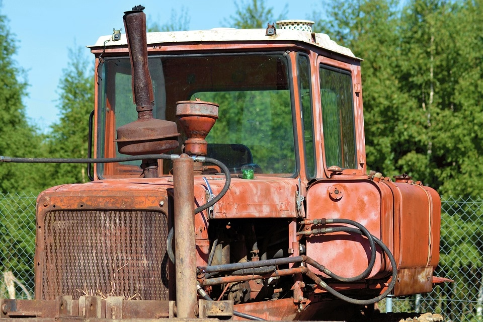
Lightweight ribs and mounts where wall thickness drives weight. We machine to ±0.005 mm and supply inspection reports with the shipment.
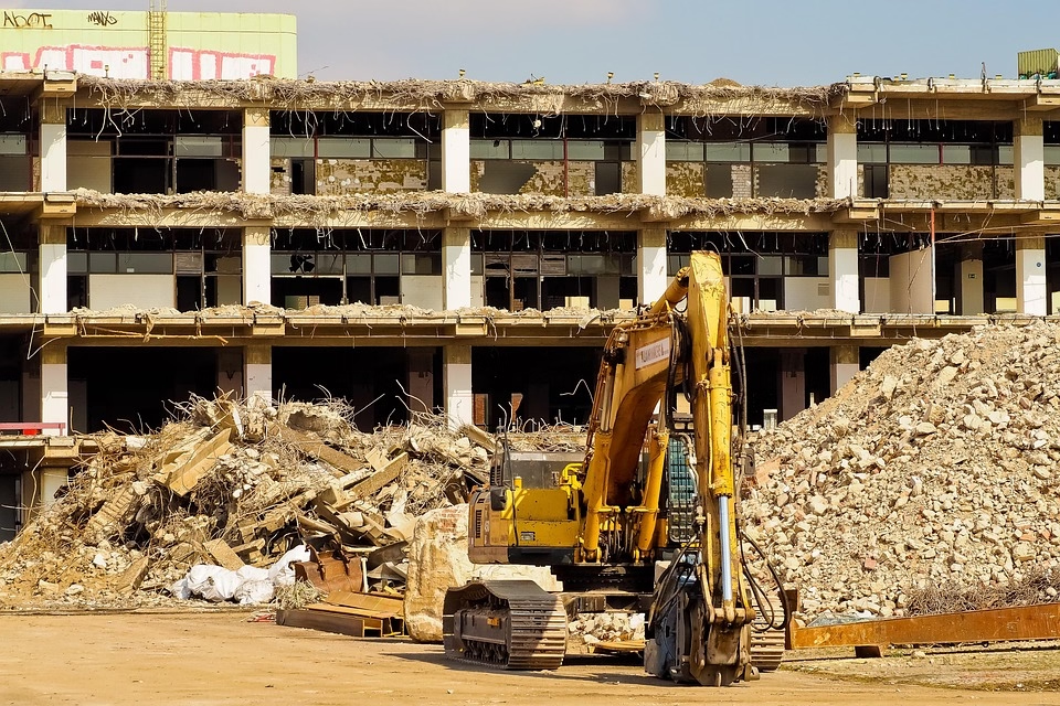
Check fixtures and housing prototypes that must survive repeated clamping. Printed mockups first, then milled or turned production parts.
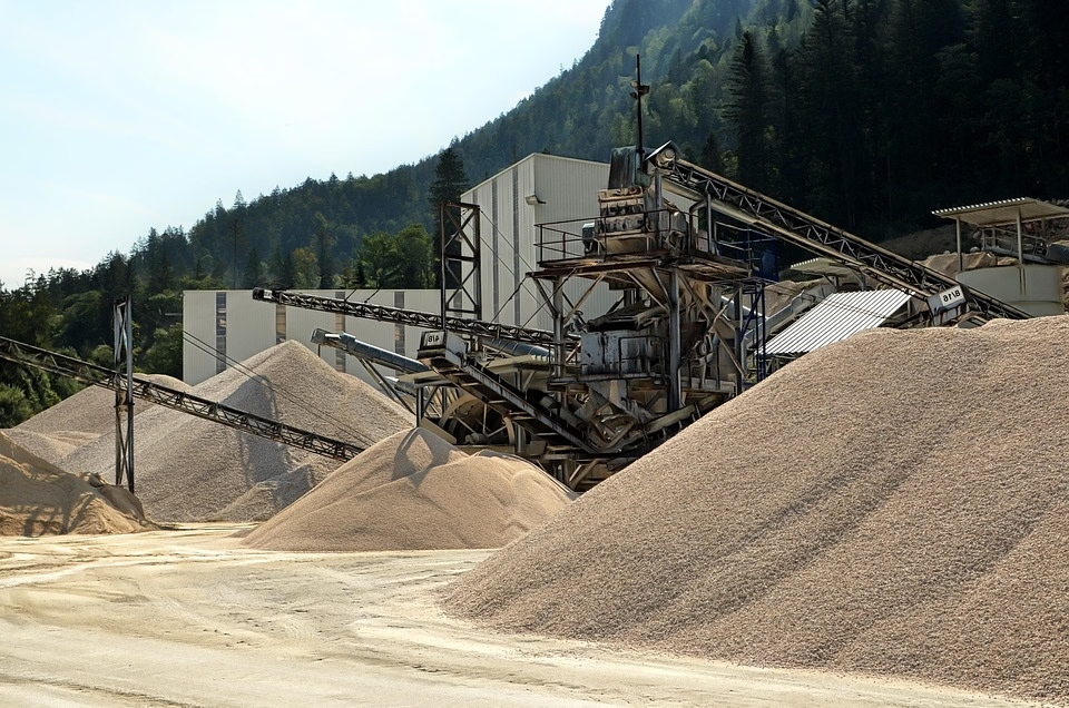
Enclosures and instrument bodies that need clean surfaces and traceable inspection. Stainless 316L and machined finishes are routine for us.
End-effector plates and gripper jaws where the bore and thread carry load. We move those features from print to CNC and hold the fit.
Authorization is a print-readiness gate, not a certificate. The gate opens when three things line up: a watertight mesh the slicer accepts, a material that matches the service temperature and load, and a build envelope that fits the part without splitting it.
In practice you clear the gate by submitting the model for review. Send the STL or STEP with the load case and we return marked-up notes on thin walls, support placement and holes below the drill minimum. Once the geometry is corrected, every later run of that part is a known build.
STL is the usual print format, and STEP is better when the part may end up machined instead, because STEP keeps true arcs and hole diameters. Keep units in millimeters and avoid scaling on export.
If your CAD only writes OBJ or a mesh format, send it anyway. We can repair open edges and flipped normals during the DFM pass, though a repaired mesh sometimes shifts a surface by a few hundredths of a millimeter.
For a 0.6 mm nozzle, keep walls at 0.8 mm or thicker. A 0.4 mm wall on that nozzle either prints porous or disappears from the tool path. Small features such as ribs and snap hooks should be sized to the nozzle, not to the CAD grid.
If the wall must stay below 0.8 mm, we either switch to a smaller nozzle, which raises build time, or move the part to CNC machining where a 0.5 mm wall in aluminium 6061 can be cut with light passes.
Printing loses when a feature carries a precision fit or a repeated load. A bearing bore, a press-fit pin, a thread under clamp load or a sealing face all need metal-grade tolerance, and printed polymer will not hold ±0.005 mm across temperature cycles.
The same applies above roughly 150 °C service, where only PEEK-class material survives and the cost climbs. In those cases we quote the part in aluminium, stainless or steel and machine it instead. We will tell you which route is cheaper before you commit.
Yes, and that is the common path. The printed piece proves the form and the fit. The machining quote uses the same CAD model, so the metal part keeps the interface dimensions the prototype validated.
We hold ±0.005 mm on machined features and inspect 100% before shipment, with reports on request. A single prototype and a 10,000-part run use the same inspection route. There is no minimum order quantity.
Quotation and free DFM analysis come back within 12 hours of upload. Production can start within 24 hours of release, and parts ship in 3–5 days.
That timing assumes the file clears review on the first pass. If the DFM notes need a CAD change on your side, the clock restarts when the corrected model lands. Our historical late-delivery probability stays below 2%.
Yes. Uploads are kept secure and confidential, and we sign a non-disclosure agreement on request before any file reaches the shop floor.
If your model carries a customer drawing number or a controlled interface, tell us in the message. We keep the document set separate and release it only to the engineers quoting the job.
Yes. There is no minimum order quantity, from one prototype to 10,000+ part runs. A single printed mockup or one machined sample is a normal order.
For batch production we provide a free sample for check before mass production. That sample runs on the same machines and inspection route as the full order, so the check is meaningful.
Upload your STL or STEP and get a free DFM analysis plus a quote within 12 hours. One piece or ten thousand, the review is the same.
12-hour quote100% inspectionNo minimum order quantity
Trusted by engineers and manufacturers worldwide










Upload your 3D model or 2D drawing and get a quotation with a free DFM analysis. Maximum processing size 4,000 mm.
CNC Metals 13 grades
CNC Plastics 10 grades
Machines & processes 12 options
Surface & post-processing 10 options
Material: not selected Machine: not selected Post-process: not selected
Fill in this short form and we'll open WhatsApp with your message ready to send. We only use these details to reply to you.
Nothing is sent until you press send inside WhatsApp.