
How CNC Router Machine Works: A Step-by-Step Cutting Guide
A CNC router moves a spinning tool along X, Y and Z under G-code control. This guide is for engineers and buyers who need to know whether a router fits a job, and how to set one up without scrapping the first sheet.
In this article
- 1
- 2
- 3
- 4
- 5
- 6
- 7
- 8
Key takeaways
How CNC Router Machine Works: Motion, Control and Cutting
A CNC router is a Cartesian machine. The spindle sits on a gantry that travels in X and Y, and a Z axis raises or lowers the tool. Each axis has a motor, a screw or rack and pinion, and a linear rail. The controller sends pulses to the drives, the drives turn the motors, and the tool follows the coordinates in the program.
The program is G-code. CAM software takes a CAD model and slices it into passes, then writes lines such as G1 X120.5 Y45.0 F3000. The controller reads one line at a time, plans a look-ahead buffer, and issues step and direction signals. Nothing is measured by hand during the cut, so repeatability comes from the machine, not the operator.
Cutting happens at the tool tip. The spindle spins a carbide cutter at 12,000 to 24,000 rpm for wood and plastics, and at lower rpm for aluminum. The flutes shear material away, and the chips carry heat out of the cut. If chips recut, the edge burns and the tool wears fast. Chip evacuation matters as much as spindle speed.
A router is not a milling machine. Its gantry is long and light so it can span a full 4,000 mm sheet, and that geometry trades stiffness for reach. On plywood and foam the trade is invisible. On steel it shows up as chatter, poor finish, and tool breakage.
- 1X and Y carry the tool over the workGantry routers move the bridge; moving-table routers move the sheet under a fixed bridge.
- 2Z sets depth of cutZ is the shortest axis and the least stiff. Keep tool overhang short.
- 3The controller holds the pathLook-ahead smoothing keeps corners from overshooting at high feed rates.
The Parts That Decide Accuracy
The frame and gantry set the ceiling on accuracy. Steel weldments damp vibration; aluminum extrusion flexes. A machine that holds ±0.05 mm on a 1,200 mm span is doing well. GreatLight holds ±0.005 mm on metal parts, but that comes from 16 simultaneous 5-axis machining centers, not from a router.
The spindle is the second limit. Router spindles run on ceramic bearings and are built for high rpm, not high torque. A 3 kW to 6 kW spindle cuts MDF and acrylic all day. The same spindle stalls in aluminum at a 6 mm depth of cut. Match spindle power to material before you match anything else.
Linear motion hardware decides smoothness. Precision-ground rails and preloaded bearing blocks give low friction and tight tracking. Rack and pinion drives are fast and cheap over long spans. Ball screws are more accurate over short spans. Most large routers use rack and pinion on X and Y, and a ball screw on Z.
The controller and software close the loop. The controller interprets G-code and manages feed, spindle speed, and tool changes. CAM settings decide stepover, stepdown, lead-in type, and tab placement. A good post-processor keeps the machine out of trouble at corners and ramps in gently.
- 1Vacuum table or fixtureVacuum holds flat sheet; clamps or a fixture hold 3D parts and small blanks.
- 2Dust and chip extractionOn composites, extraction protects the operator and keeps the cut clear.
- 3Tool setter and probingA tool setter removes manual zero errors between jobs.
Which Materials Suit a Router, and Which Do Not
Routers do their best work in sheet goods and soft stock. MDF, plywood, solid wood, acrylic, polycarbonate, ABS, HDPE, foam, and carbon fibre laminate all cut cleanly at 12,000 to 18,000 rpm. Depth per pass runs 3 mm to 8 mm depending on tool diameter and spindle power.
Aluminum is the practical limit. 6061 and 5052 cut with a single-flute or 2-flute carbide tool at 8,000 to 12,000 rpm, 0.5 mm to 1.5 mm depth per pass, and a light mist or air blast. Feed rates of 1,500 to 3,000 mm/min work on a stiff machine. Anything deeper invites chatter and a welded edge.
Steel, stainless, titanium and Inconel do not belong on a router. Low spindle torque, long tool overhang, and a flexible gantry combine badly. These materials need a machining center with a rigid spindle and flood coolant. We run them on 3-axis, 4-axis and 5-axis mills, not on routers.
Part geometry also decides. Flat parts with through-cuts, shallow pockets, and large radii are ideal. Tall thin walls, deep narrow pockets, and tight internal corners are not. If the tool cannot reach the corner, the design needs a corner radius or a different process.
- 1Good fitSignage, panels, enclosures, jigs, prototypes, and composite trim.
- 2Marginal fitThin aluminum plates, shallow pockets, and low-volume brackets.
- 3Wrong fitSteel molds, deep cavities, and parts needing Ra 0.2–0.8 μm.
Workholding and Zeroing Before the First Cut
Workholding decides whether the cut is accurate. A vacuum table pulls a flat sheet down evenly, which suits nested parts and full-sheet jobs. For small or 3D parts, use clamps, a vacuum pod, or a machined fixture. Any movement of 0.1 mm under load shows up in the finished edge.
Zero the machine in the right order. Touch off X and Y against a known datum, then set Z on the top of the stock. Use a tool setter for every tool in the program. Manual Z zeroing is the most common source of scrapped first parts, especially after a tool change.
Check the program before the spindle starts. Run the toolpath in air with the Z raised, or use a simulation with the stock model. Look for rapid moves that pass through the part, missing tabs, and plunge moves that enter at full depth.
Set the dust shoe and the extraction before cutting composites. Fine dust from carbon fibre and MDF is a health hazard and it also recuts under the tool. Good extraction gives a cleaner edge and longer tool life at the same parameters.
- 1Flatness firstSurface the spoilboard before a tight-tolerance job.
- 2Tabs for small partsLeave 0.5–1.0 mm tabs so parts do not shift on the last pass.
- 3Record the offsetsSave fixture offsets so the next run repeats without re-zeroing.
Step by Step: From CAD to Finished Part
Parameters below suit a 3 kW to 6 kW gantry router.
- 11. Prepare the CAD modelModel the finished part, then add tool radius clearance at internal corners. Export STEP or DXF at 1:1. Check that the smallest internal radius is at least half the cutter diameter.
- 22. Build the CAM toolpathChoose the cutter, then set stepdown and stepover. For MDF and acrylic use 3–6 mm stepdown and 40–50% stepover. For aluminum use 0.5–1.5 mm stepdown and 30–40% stepover.
- 33. Set feeds and speedsWood and plastic: 12,000–18,000 rpm, 3,000–6,000 mm/min. Aluminum: 8,000–12,000 rpm, 1,500–3,000 mm/min. Start conservative and raise feed until the chip looks like a chip, not dust.
- 44. Add lead-ins, ramps and tabsRamp or helix into the material instead of plunging straight down. Add 0.5–1.0 mm tabs on small parts. Set lead-in radius to about 50% of tool diameter on outside profiles.
- 55. Mount and level the stockSeat the sheet on the vacuum table or fixture and check flatness with a dial indicator. Surface the spoilboard if the job needs tight flatness. Clamp 3D parts so they cannot lift.
- 66. Zero the axes and load toolsTouch off X, Y and Z on the datum. Set every tool with the tool setter. Confirm the tool numbers in the program match the carousel positions.
- 77. Dry run, then cut the first partSimulate or air-run the path with Z raised. Cut one part, measure it, and adjust tool radius compensation or offset before running the batch. Measure again after the last part.
Router Parameters by Material
Starting points for a 3–6 kW gantry router with carbide tooling.
| Material | Tool | Spindle speed | Depth per pass |
|---|---|---|---|
| MDF, plywood | 2-flute upcut, Ø6 mm | 16,000–18,000 rpm | 4–8 mm |
| Solid wood | 2-flute upcut, Ø6–12 mm | 12,000–16,000 rpm | 3–6 mm |
| Acrylic, PMMA | 1-flute O-flute, Ø6 mm | 14,000–18,000 rpm | 2–4 mm |
| ABS, HDPE | 2-flute upcut, Ø6 mm | 12,000–16,000 rpm | 3–5 mm |
| Carbon fibre laminate | Diamond-cut, Ø6 mm | 12,000–15,000 rpm | 1–2 mm |
| Aluminum 6061 | 1-flute or 2-flute, Ø6 mm | 8,000–12,000 rpm | 0.5–1.5 mm |
| Steel, stainless, titanium | Not recommended | Not recommended | Not recommended |
Router vs Machining Center: When to Switch
| Criterion | CNC router | CNC machining center |
|---|---|---|
| Typical material | Wood, plastic, composite, aluminum | Steel, stainless, titanium, aluminum |
| Work envelope | Up to 4,000 mm sheet | Up to 4,000 mm travel |
| Holding tolerance | ±0.05 mm on sheet goods | ±0.005 mm on metal |
| Surface finish | Ra 1.6–3.2 μm as machined | Ra 0.2–1.6 μm with finishing passes |
| Best part shape | Flat, through-cut, shallow pocket | 3D contour, deep pocket, tight corner |
| Typical volume | One-off to low hundreds | Prototype to 10,000+ parts |
Router or machining center?
Use a router for flat sheet, plastic, composite and light aluminum work. Move to a machining center when the material is hard, the pocket is deep, or the tolerance is ±0.005 mm. Send us the drawing and we will tell you which process fits.
Common questions
Can a CNC router cut aluminum?
Yes, within limits. 6061 and 5052 plate up to about 10 mm cut well with a single-flute or 2-flute carbide tool, 0.5 to 1.5 mm depth per pass, and air or mist cooling.
The catch is rigidity. A light gantry will chatter before the spindle runs out of power, so keep tool overhang short and reduce depth until the cut sounds steady.
What tolerance can I expect from a router?
On sheet goods, ±0.1 mm is realistic on a well-maintained machine, and ±0.05 mm on a stiff gantry with a surfaced spoilboard.
If the drawing calls for ±0.005 mm, the part belongs on a machining center. Tolerance follows machine stiffness, not the controller.
Why does my first part come out undersized?
Tool radius compensation is usually the cause. If CAM does not offset the path by half the cutter diameter, every outside profile shrinks by that amount.
Check cutter diameter in the tool library against the actual tool, then measure the first part before running the batch.
Why does the top face tear out?
An upcut tool lifts fibres on the top surface. Switch to a downcut or compression tool for the finishing pass, or add a sacrificial board on top.
Dull tooling and too high a feed rate make it worse. Replace the cutter when the edge stops looking clean.
Do I need a vacuum table?
For nested sheet work, yes. Vacuum holds the whole sheet flat and lets you cut through without clamps in the path.
For 3D parts and small blanks, a fixture or vacuum pods work better. Vacuum loses grip on small, curved parts.
When should I send the job to a machine shop instead?
Send it out when the material is steel, stainless, titanium or Inconel, when walls are thin and tall, or when the finish spec is Ra 0.8 μm or finer.
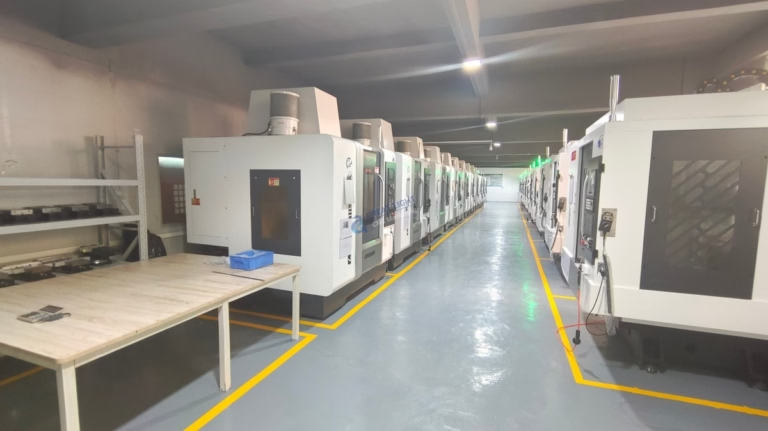
GreatLight runs 127 high-precision CNC machines, including 16 simultaneous 5-axis centers, and quotes with DFM feedback within 12 hours.
Send your drawing, get a quote in 12 hours
Free DFM analysis with every quote. Prototype or 10,000 parts, no minimum order quantity.
12-hour quote100% inspectionNDA on request
More machining notes
We publish setup notes, tooling trials and inspection data from the factory floor.











