
How Has CNC Machining Improved Products?
A working answer for design engineers and buyers: which product-level gains come from CNC, which numbers prove them, and when a machined part is the wrong call. Read it before you lock a drawing or a supplier.
In this article
- 1
- 2
- 3
- 4
- 5
- 6
- 7
- 8
Key takeaways
What Actually Changed in CNC Machining
CNC machining is subtractive: a rotating cutter removes material from a solid billet under program control. Nothing about that idea is new. What changed is the control side. Servo drives, linear guides and thermal compensation let a modern machine follow a tool path within microns and then repeat it on the next part without a human turning a handwheel.
The product-level effect is easier to name than the machine-level one. Dimensions that used to be toleranced loosely because they could not be held are now toleranced tightly because they can. That single shift is where most of the improvement in finished products starts.
Three inputs decide the result: the machine, the fixture and the tool. A 5-axis center can reach five faces in one setup, so the part is not re-datumed four times. A stiff fixture stops the wall from springing away from the cutter. A correct cutter and feed rate decide whether the surface comes off clean or smeared.
Improvement is not automatic. A tight tolerance on a drawing that no process can inspect is not an improvement, it is a cost. The gains below only appear when the drawing, the process and the inspection method agree with each other.
Tighter Tolerances That Fix Real Product Problems
A tolerance is only useful if it controls a function. On a hydraulic manifold, the bore diameter and its roundness decide whether the seal weeps. On a gearbox housing, the center distance between two bearing bores decides noise and bearing life. On a camera mount, flange flatness decides whether the image plane tilts.
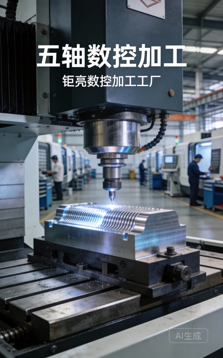
A 5-axis machining center at GreatLight holds ±0.005 mm on critical features. That is enough to press-fit a bearing without shims, seat an O-ring in a groove with a defined squeeze, and keep two mating faces flat enough that a gasket is optional rather than mandatory.
Inspection matters as much as cutting. A dimension that is measured with calipers is not a controlled dimension. Use a coordinate measuring machine or a bore gauge for anything under ±0.02 mm, and ask for the report with the parts.
The trap is over-tolerancing. Every added decimal digit raises machining time, scrap risk and inspection cost. Tolerance only the features that touch another part or carry a seal. Leave cosmetic surfaces at Ra 3.2 μm and let the shop run faster.
Part Consolidation and Weight Reduction
Machining from one billet lets you put features where an assembly could not. A bracket can carry its own mounting bosses, a wire clip, a lightening pocket and a stiffening rib in a single solid. Each bolted joint you delete removes a fastener, a washer, a torque step and a leak path.
Weight usually falls with the joint count. Pockets and ribs remove material where stress is low, and the remaining skin carries the load. An engine bracket or a robot arm link that was a weldment of five plates often becomes one machined 7075 or 6061-T6 piece that is lighter and stiffer.
There is a limit. A monolithic part must still be reachable by a cutter. If a pocket needs a tool with a length-to-diameter ratio beyond roughly 4:1, chatter and taper appear, and the pocket may need electrical discharge machining instead.
Consolidation also changes the supply chain. One part number instead of six shortens the bill of materials, cuts incoming inspection and removes assembly fixtures. For low and mid volume, that is often the larger saving.
Repeatability, Surface Finish and Fit at Volume
A verified program makes part number 5,000 match part number 1. On a machined part, that means the same bore, the same flatness and the same thread depth every cycle. Products stop varying between units, which is what supply chains for pumps, actuators and instruments actually need.
Surface finish is set during the finishing pass. A light finishing cut with a sharp tool and correct feed leaves Ra 0.8–1.6 μm on most aluminum and steel, and Ra 0.2–0.8 μm when a fine finishing pass is planned in. If the drawing calls for Ra 0.4 μm, say so before the tool path is written, not after the parts arrive.
Fit follows finish. A shaft at the top of its tolerance and a bore at the bottom still assemble if both were cut on the same machine with the same thermal state. Mixed processes and mixed shops are where interference fits go wrong.
Plan the finish early. Adding a polishing step after machining can round an edge that was specified sharp, close a small hole and change a sealing face. Design the tool path so the surface comes off the machine at the specified texture.
Materials and Finishes That Carry the Improvement
Material choice decides whether a tight tolerance stays tight. Aluminum 6061-T6 and 7075 machine cleanly and hold size well. Stainless 304 and 316 work-harden, so light cuts and constant feed are needed. Titanium TC4 (Ti-6Al-4V) and Inconel cut hot, wear tools fast and need lower surface speed, which raises cost per part.
For housings and covers, plastics such as POM, PEEK and PC remove the corrosion problem and cut weight. PEEK holds dimension better than most plastics at temperature. ABS and PP are cheaper but move more after machining, so leave a stress-relief step if the tolerance is under ±0.05 mm.
Finishing should be chosen for the function. Anodizing gives wear resistance and color. Hardcoat anodizing adds a thicker oxide for sliding surfaces. Electroless nickel gives uniform coverage on complex geometry where electroplating would build up on edges.
Say the finish before quoting. A hardcoat layer grows the part by tens of microns and can close a fine thread. Bead blasting softens an edge radius. Both are easy to plan in and expensive to undo.
How to Turn a Design Into an Improved Product
Seven steps from drawing to inspected parts
- 11. Separate functional from cosmetic featuresMark every feature that touches another part or carries a seal. Give those the tight tolerance. Leave the rest at Ra 3.2 μm and general tolerance. This alone often cuts cost by a visible margin.
- 22. Pick the datum before the geometryChoose a face and two holes that exist in the raw stock or can be cut in the first setup. Every later dimension should chain from that datum. Datums added late force extra setups and stack error.
- 33. Check tool reach on the modelLook at every pocket, slot and internal corner. Keep internal corner radii at least one third of the pocket depth where possible, and keep deep pockets under about 4:1 depth-to-diameter.
- 44. Set the process before the quoteDecide 3-axis, 4-axis or 5-axis from the number of faces and the angle between them. Parts with features on five sides belong on a 5-axis center in one setup, not on three separate fixtures.
- 55. Ask for DFM before cutting metalSend the 3D model and a 2D drawing with tolerances. GreatLight returns a quotation and a free DFM analysis within 12 hours. Fix wall thickness, sharp corners and thread depth at this stage.
- 66. Prove the first articleCut one part, measure the critical features and compare against the drawing. Adjust cutter compensation and feeds before the batch runs. Do not release the batch until the first article passes.
- 77. Lock the inspection planWrite down which features are measured, with what instrument and how often. At GreatLight every part is inspected before shipment, with raw material, in-process and final checks, and reports on request.
When a Machined Part Is the Right Answer
Match the feature to the process before you commit
| Product feature | Best process | Why |
|---|---|---|
| Sealing face, flat within 0.01 mm | CNC machining | Ground or fine-milled flatness holds a gasket seal |
| Bearing bore under ±0.01 mm | CNC machining | Boring on one machine keeps roundness and fit |
| Thin free-form shell, wall under 1 mm | Casting or molding | Machining deflects the wall and wastes material |
| Hollow internal cavity, no access | Casting or 3D printing | A cutter cannot reach an enclosed volume |
| Sharp internal corner, radius under 0.5 mm | EDM or casting | End mills leave a radius equal to their corner |
| 10,000 identical simple parts | Die casting or molding | Tooling cost spreads over volume |
| One prototype to 10,000+ mixed parts | CNC machining | No tooling, program change is quick |
The Short Answer
CNC machining improves a product when it holds a functional tolerance, removes a joint or sets a surface the product actually needs. If a feature does none of those three, a cheaper process is the better choice.
Frequently Asked Questions
How has CNC machining improved products without raising cost?
Most of the saving comes from removing parts, not from cutting faster. A single machined bracket replaces a weldment, so fasteners, assembly time and inspection steps disappear.
The second saving is scrap. A proven program holds ±0.005 mm, so fewer parts are rejected at final inspection. That is where tight tolerance pays for itself.
Is ±0.005 mm realistic on every feature?
No. It is realistic on a critical bore, face or slot that is cut in a controlled setup and measured properly.
Applying it to every dimension multiplies machining and inspection time. Keep general tolerances loose and put the tight callout only where a seal, bearing or mating face needs it.
What is the largest part you can machine?
GreatLight machines parts up to 4,000 mm in the largest travel. Common envelope sizes are 4,000 × 400 × 150 mm, 750 × 1,150 × 550 mm and 600 × 600 × 600 mm.
Small work runs on 500 × 500 × 450 mm and 500 × 310 × 200 mm travels, with a Ø400 mm rotary table for round features.
Which materials give the best result for a tight tolerance?
Aluminum 6061-T6, 7075 and stainless 17-4PH hold size well and are easy to inspect. They are the default for housings, brackets and manifolds.
Titanium TC4 and Inconel can also be held to ±0.005 mm, but tool wear and heat mean slower cutting and a higher part price. Budget for that up front.
How do I know the parts will match the drawing?
Ask for the inspection plan with the quote. At GreatLight every part is inspected before shipment, with raw material check, in-process monitoring and final inspection, and reports on request.
For anything under ±0.02 mm, agree on the measuring instrument before production starts. Calipers and CMM reports are not the same evidence.
Can you start before I finish the drawing package?
Yes. Send the 3D model and whatever 2D information you have. We return a quotation and a free DFM analysis within 12 hours, then production can start within 24 hours of approval.
Uploads are secure and confidential, and an NDA is available on request.
Send the Drawing, Get a DFM Review
Upload your model and drawing. We return a quotation and a free DFM analysis within 12 hours, then start production within 24 hours of approval.
12-hour quote±0.005 mm tolerance100% inspectionNo minimum order quantity
More machining notes
We publish setup notes, tooling trials and inspection data from the factory floor.











