
How to Make a 3D CNC Milling Machine
This guide covers the frame, linear motion, spindle, electronics and control chain you need to make a 3D CNC milling machine that cuts metal, not just foam. It is written for engineers and hardware teams who want to judge whether a build is worth the time. By the end you can pick a sensible travel envelope and know where a self-built machine stops and a production shop starts.
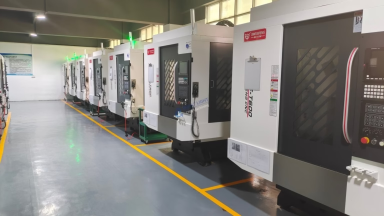
What matters before you buy a single part
What a 3D CNC milling machine actually is
A 3-axis mill moves a spinning cutter along X, Y and Z while the workpiece stays clamped. The word 3D here means the toolpath can reach any point in a three-dimensional volume, not that the machine prints or adds material. Every cut is subtractive: the cutter removes chips and the finished shape is whatever is left.
Three numbers define the machine more than any spec sheet. Travel is how far each axis can move. Stiffness is how much the frame deflects under cutting force. Accuracy is how close the tool tip lands to the commanded point. You can buy accuracy with better screws, but stiffness comes from the structure, and no controller setting can fix a frame that flexes.
When you make a 3D CNC milling machine for aluminium, the cutting force at the tool tip can reach several hundred newtons. That force pushes back through the cutter, the spindle, the Z column and the base. If any link in that chain bends by 0.1 mm, the finished wall will show it. This is why machine builders spend most of their budget on cast iron, steel plate and large linear rails rather than on a faster controller.
- 1TravelThe usable stroke of each axis, measured without hitting hard stops.
- 2StiffnessDeflection per unit of cutting force. The dominant limit on depth of cut.
- 3AccuracyHow close the tool tip follows the commanded path after backlash and screw error.
Frame, motion and spindle choices
The frame sets the ceiling for everything else. Steel plate bolted and doweled, welded steel with stress relief, or epoxy granite all work. Aluminium extrusion is cheap and easy to drill, but it flexes under load and its T-slots loosen over time. For a machine that only cuts plastic and wood, extrusion is fine. For aluminium, use at least 10 mm steel plate on the column and base.
Linear motion has two common answers. Profile rails on a machined shoulder give high stiffness and take preload. Round rail on supported shaft is cheaper but deflects more in the middle of travel. Ballscrews with C7 accuracy are the practical choice for a first build; ground C5 screws cost more and only pay off if the frame is already stiff.
The spindle decides what materials you can cut. A 1.5–2.2 kW water-cooled spindle with an ER20 or ER25 collet runs 6,000–24,000 rpm and handles 6061 aluminium with a 6–10 mm end mill. A trim router spins fast but has weak bearings and no torque at low rpm. If you plan to cut steel, you need a much heavier spindle and a machine frame to match it, which usually means this build is the wrong path.
Think about chip evacuation before you cut the first part. Aluminium chips pile up fast and recut if they are not cleared. A shop vacuum at the cutter plus a small air blast solves most of it. Flood coolant is better for deep pockets but adds a pump, a tray and a mess you have to manage.
- 1Steel plate frame10 mm or thicker, doweled and bolted. Best stiffness per dollar for a first build.
- 2Profile railsPreloaded carriages on a machined shoulder. Less mid-travel deflection than round rail.
- 3C7 ballscrewsGood enough for most builds. Upgrade to C5 only after the frame is stiff.
- 41.5–2.2 kW spindleWater cooled, ER20 collet, 6,000–24,000 rpm. The practical floor for aluminium.
Motors, drivers and the control chain
Stepper motors are the default for a first build. NEMA 23 motors with 3 N·m holding torque drive a 5 mm pitch ballscrew hard enough for a small mill. Closed-loop steppers cost a little more and recover from lost steps, which matters when a deep cut stalls an open-loop motor and the rest of the program runs in the wrong place.
The driver and controller form one chain. A digital driver at 48–60 V DC gives more speed than a 24 V supply. The controller turns G-code into step and direction pulses. GRBL runs on an inexpensive board and covers 3 axes well. LinuxCNC runs on a PC and adds rigid tapping, tool changers and full 4-axis work when you need it.
Wiring is where most first builds fail. Stepper cables must be shielded and the shield grounded at one end only, or noise from the spindle drive will trigger false steps. Keep signal wires away from motor and spindle power cables. Route them in separate cable carriers if you can. A single bad ground loop can make a machine that cuts perfectly in air and randomly scraps parts under load.
Limit switches and a probe are cheap insurance. Hard limits stop the machine before it crashes into a hard stop at full speed. A touch probe lets you set the workpiece zero in seconds instead of edge-finding by eye. Neither changes the cut, but both change how often you ruin a part.
- 1NEMA 23, 3 N·mEnough torque for a small mill on 5 mm pitch ballscrews.
- 248–60 V DC supplyMore voltage means more speed before the motor torque falls off.
- 3Shielded cablesGround the shield at one end only to avoid ground loops.
- 4Hard limits and probeCheap parts that prevent crashes and speed up setup.
Step by step: from CAD to first chips
- 11. Model the whole machine in CADDraw the frame, rails, screws, spindle and the largest workpiece you expect. Check that the spindle nose can reach every corner of the travel envelope at full Z extension. Look for interference at the extremes, not just at the middle. Most redesigns happen here, and they are free.
- 22. Set the travel envelope from your real partMeasure the largest part you will cut, then add 100 mm on X and Y for clamps and tool clearance. For Z, add the longest tool plus the fixture height to the part height. A common compact envelope is 500 × 500 × 450 mm. Oversizing travel costs stiffness, so do not add margin you will never use.
- 33. Machine and assemble the frameHave the plate surfaces machined flat and the rail mounting shoulders milled in one setup. Bolt and dowel the joints, then check squareness with a dial indicator. Aim for under 0.02 mm over 300 mm. Shim or scrape the rail shoulders until the two rails of an axis are parallel within 0.01 mm.
- 44. Mount rails, screws and carriagesBolt the rails down gradually, moving from the center outward, and torque in stages. Install the ballscrew with a fixed angular-contact bearing at the motor end and a floating support at the far end. Check backlash at the nut with a dial indicator; anything over 0.02 mm needs attention before you cut.
- 55. Build the spindle mount and Z columnThe Z column carries the most bending load. Use a plate at least 16 mm thick, or a box section. Mount the spindle with a clamp that wraps at least 60 percent of its body. Check runout at the tool holder with a dial indicator: under 0.01 mm TIR is a good target.
- 66. Wire the electronics and test each axisWire one axis at a time and jog it at low speed before running the next. Set motor current to about 70 percent of the rated value and tune acceleration until the axis moves without stalling. Test at 50 mm/min first, then step up. Home the machine and confirm that the soft limits match the real travel.
- 77. Tram the spindle and cut a test partTram the spindle to the table within 0.02 mm over 200 mm. Face a scrap plate, then measure flatness and stepover marks. Start with a 6 mm 3-flute carbide end mill in 6061 aluminium at 8,000 rpm, 0.5 mm depth of cut and 800 mm/min feed. Increase depth only when the chips look right and the machine does not chatter.
Self-built machine vs. job-shop machining
Use this table to decide where a build makes sense and where it does not.
| Factor | Build it yourself | Send it to a machine shop |
|---|---|---|
| Best for | Learning, one-off lab fixtures, soft materials | Production parts, tight tolerance, hard materials |
| Typical tolerance | 0.05–0.1 mm with care | ±0.005 mm on 5-axis centers |
| Materials | Plastic, wood, aluminium, light cuts | Aluminium, steel, titanium, Inconel, plastics |
| Upfront cost | Frame, rails, spindle, electronics | No capital cost, pay per part |
| Time to first part | Weeks to months of build and tuning | Quotation in 12 hours, parts in 3–5 days |
| Setup effort | You own every crash and backlash fix | DFM feedback and inspection reports included |
| Scaling | One machine, one operator | From one prototype to 10,000+ parts |
| Best when | You need to learn and iterate on the machine | You need parts that fit the first time |
Questions engineers ask before building
Can a self-built 3D CNC milling machine cut steel?
It can scratch steel, but not productively. Steel needs low surface speed and high cutting force, so the spindle must run slowly with real torque and the frame must resist that force without deflecting.
A light build will chatter, burn tools and produce a poor surface. If steel is a regular requirement, use a heavier machine or send the parts out. Aluminium and plastics are the realistic target for a first build.
How much does it cost to build one?
Cost depends on the frame material, rail grade and spindle. The frame and linear motion usually take the largest share, followed by the spindle and the electronics.
A rough budget split is frame and motion first, spindle second, electronics third, with tooling and workholding as a fourth line item people forget. Add 15–20 percent for mistakes and rework.
Do I need ballscrews or is lead screw enough?
Lead screw is fine for a light machine cutting plastic and wood. It has more friction and more backlash, which shows up as poor surface finish and inconsistent dimensions.
For aluminium, ballscrews with C7 accuracy are the practical choice. Check backlash at the nut after assembly and keep it under 0.02 mm. Preloaded nuts reduce it further.
Which controller software should I start with?
GRBL on a low-cost board is the shortest path to a working 3-axis machine. It is simple, well documented and enough for milling with a fixed tool.
Move to LinuxCNC when you want rigid tapping, a tool changer or full 4-axis work. Both accept standard G-code, so the CAM side does not change.
How do I know when the machine is accurate enough?
Cut a test part with known dimensions, then measure it on a calibrated instrument. Check flatness on a faced surface, parallelism between two machined faces and the position of a drilled hole.
If the error repeats, it is mechanical: backlash, screw pitch error or frame deflection. If it varies, look at tool runout, workholding or thermal growth during a long cut.
Should I build a machine or just order machined parts?
Build if the goal is to learn, to own the capability, or to iterate on fixtures that change often. Order machined parts when the geometry is fixed and the tolerance matters.
A shop with 127 high-precision CNC machines, 16 simultaneous 5-axis centers and ±0.005 mm capability covers work a first build cannot reach. Many teams do both: build for learning, order for production.
Need parts while your build is still on the bench?
Send your CAD files and get a quotation with free DFM analysis within 12 hours. No minimum order quantity, from one prototype to 10,000+ parts, with 100% inspection before shipment.
12-hour quote100% inspectionNo MOQ
More machining guides
We publish setup notes, tooling trials and inspection data from the factory floor.











