
How to Make Arduino CNC Milling Machine
Build an Arduino CNC milling machine that runs on GRBL, three stepper drivers and a 24 V supply. This guide is for builders who want real numbers: axis travel, step/mm, motor current, acceleration, and the first cuts in 6061 and POM.
Key takeaways
Pick a Frame Before You Buy Motors
An Arduino CNC milling machine is only as rigid as the gantry that carries the spindle. V-slot extrusion in 2020 or 2040 profile is the common starting point because it bolts together without welding and stays square within about 0.2 mm over a 400 mm span. Steel plate gantries are stiffer but need a drill press and a way to true the faces.
Work out the travel you actually need. A 300 × 200 × 80 mm work envelope handles most prototype brackets, small panels and enclosure plates. Every extra 100 mm of X travel adds mass to the gantry, and the stepper that moved a 300 mm axis easily will start skipping steps at 500 mm unless you go up a frame size.
The Z axis is where most first builds lose accuracy. A short Z column, 80–120 mm of travel, with the spindle mounted as close to the gantry as the tool holder allows, cuts chatter dramatically. Long Z plates act like a lever and show up as a tapered wall on deep pockets.
Leave room for a spoilboard and clamps. Subtract 20 mm of Z for the fixture plate and another 10 mm for the tool stick-out. Builders who forget this end up with 40 mm of usable Z on a 100 mm axis and cannot hold a 6 mm end mill.
- 1RailsMGN12 or MGN15 linear rail beats unsupported rod above 200 mm span.
- 2Ballscrews1605 rolled ballscrew, C7 grade, is enough for a bench machine.
- 3Spoilboard18 mm MDF faced flat on both sides, surfaced after assembly.
Motors, Drivers and the Torque You Actually Need
NEMA 23 steppers in the 1.9–3.0 N·m range drive most hobby mills. NEMA 17 at 0.4 N·m will move a light 3018-style frame but stalls when you push a 6 mm end mill into aluminum. Match torque to the moving mass, not to the biggest motor that fits the bracket.
Set driver current to 70–80% of the motor rating. A 3.0 A motor runs at 2.1–2.4 A on a DM542 or TB6600 driver. Higher current buys a little torque and a lot of heat, which softens the motor and shifts your steps over a long job.
Microstepping is a trade. 1/8 step gives smooth motion on a 1605 ballscrew, that is 1600 steps per revolution with a 200-step motor. 1/16 doubles resolution but halves usable torque and raises the step rate your Arduino must generate. For an Arduino CNC milling machine that cuts metal, 1/8 is the safer default.
Belt drive on X and Y is cheaper and faster, but belts stretch under cutting load. If you use GT2 or GT3 belts, keep the run under 600 mm, tension to roughly 50–60 Hz on a belt tension gauge, and expect to re-tension after the first ten hours.
- 1Power supply24 V 10 A for NEMA 17 builds, 36–48 V for NEMA 23.
- 2CouplingRigid or Oldham coupling, never a flexible spring type on Z.
- 3WiringShielded motor cable, shield grounded at the driver end only.
Wiring the Arduino, GRBL and Limit Switches
GRBL 1.1 on an Uno with a CNC shield is the standard entry point. The shield maps X, Y and Z step and direction to D2–D7, with enable on D8 and the three limit inputs on D9, D10 and D11. Keep the stepper wiring away from the limit switch wiring or you will chase phantom triggers for a weekend.
Limit switches should be normally closed, wired in series per axis, and powered from the 5 V rail through a 10 kΩ pull-up if your board does not have one. GRBL's default is normally open, so you must invert the pin mask, set $5=1, or the machine will refuse to home.
E-stop is not optional. Wire a latching mushroom switch in series with the enable line so a fault drops the drivers instead of relying on software. Software stop only works while the board is alive.
Add a 100 nF capacitor across each limit input if your spindle is a brushed trim router. Brush noise couples into the switch cable and shows up as random hard limits mid-cut.
- 1Spindle controlPWM via a relay or a 0–10 V module, never straight from the Arduino pin.
- 2CoolantAir blast is enough for aluminum on a bench machine.
What an Arduino CNC Milling Machine Cannot Do
A bench machine with aluminum extrusion and rolled ballscrews holds roughly ±0.05 mm on a good day, and ±0.1 mm once thermal drift and tool wear are counted. That is fine for brackets, fixtures, prototype plates and enclosure panels. It is not fine for bearing bores, sealing faces or anything with a ±0.005 mm callout.
Step rate is the second wall. An 8-bit Arduino at 16 MHz with GRBL manages around 30 kHz, which at 320 steps/mm caps you near 5,600 mm/min of rapid. That is plenty for cutting, but it limits how fast you can move between features on a large part.
Chatter sets in before the spindle runs out of power. A 2 mm depth of cut in 6061 on a V-slot gantry will sing and leave a poor wall finish, even if the motor has torque left. Reduce depth, shorten the tool, or accept a slower job.
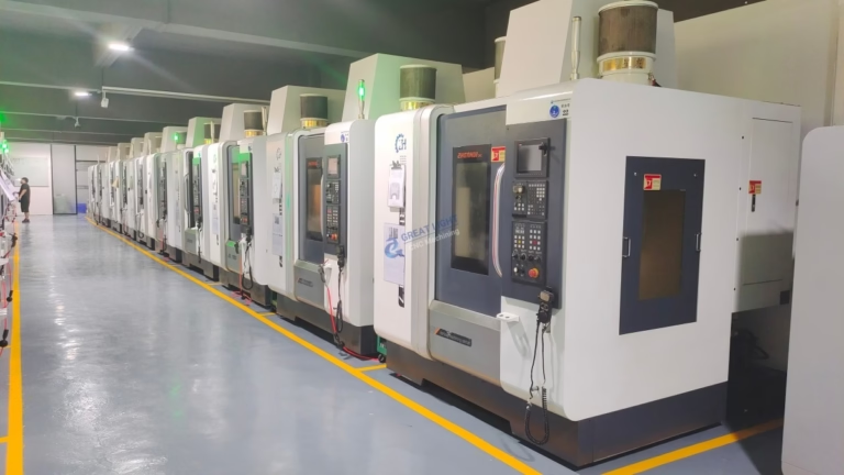
When a part needs ±0.005 mm, Ra 0.8–1.6 μm and a documented inspection report, the job belongs on a production VMC. GreatLight runs 127 high-precision CNC machines, including 16 simultaneous 5-axis centers, with ±0.005 mm tolerance and 100% inspection before shipment. That is the route for parts that carry the assembly.
- 1Keep the bench build forPrototypes, jigs, panels, fixture plates, one-off brackets.
- 2Send out forBearing fits, sealing surfaces, threaded bores, production runs.
- 3Hybrid workflowCut the geometry yourself, then have critical features finished to tolerance.
Step by Step: From Parts to First Cut
Follow this order. Skipping the squaring step is the most common reason a new machine cuts tapers.
- 11. Square the frame on a flat surfaceBolt the base and gantry loose, clamp to a granite plate or a known flat bench, and measure diagonals. Adjust until the two diagonals match within 0.1 mm, then tighten in a cross pattern.
- 22. Mount rails and check straightnessRun a dial indicator along each rail. Aim for under 0.03 mm deviation over 300 mm. Shim with 0.05 mm brass stock under the low spots rather than over-tightening the bolts.
- 33. Install ballscrews and couplingsSet screw end float to 0.02 mm or less. Spin each screw by hand through full travel; any tight spot means a misaligned bearing block, not a bad screw.
- 44. Wire drivers, Arduino and limitsSet driver current to 70–80% of motor rating and microstepping to 1/8. Keep signal wires at least 50 mm from motor power cables and cross them at 90° where they must meet.
- 55. Flash GRBL and set travelSet $130, $131, $132 to your real travel in mm, then $100–$102 to the calculated steps/mm. For a 1605 screw at 1/8 microstep with a 200-step motor, that is 1600 / 5 = 320 steps/mm.
- 66. Home and tune accelerationStart at $120–$122 = 100 mm/s², raise in 50 mm/s² steps until the machine skips, then back off 30%. Most bench builds settle between 200 and 500 mm/s².
- 77. Surface the spoilboardFace the MDF with a 6 mm flat end mill at 8,000 rpm, 600 mm/min, 0.3 mm depth. This makes the bed parallel to the spindle, not to the floor.
- 88. Cut a test part in POM, then 6061POM first at 12,000 rpm, 800 mm/min, 1 mm depth. Then 6061 at 10,000 rpm, 400 mm/min, 0.5 mm depth with air blast. Measure the part before you change any parameter.
Starting Parameters for Common Materials
Bench machine with a 1.5 kW or 800 W spindle, 6 mm two-flute carbide end mill, 1/8 microstep.
| Material | Spindle speed | Feed | Depth of cut |
|---|---|---|---|
| POM (Delrin) | 12,000 rpm | 800 mm/min | 1.0 mm |
| ABS / acrylic | 14,000 rpm | 900 mm/min | 0.8 mm |
| 6061 aluminum | 10,000 rpm | 400 mm/min | 0.5 mm |
| 7075 aluminum | 8,000 rpm | 300 mm/min | 0.3 mm |
| Brass C36000 | 9,000 rpm | 250 mm/min | 0.3 mm |
| 1018 steel | Not recommended | — | — |
Build the bench machine, but know its ceiling
An Arduino CNC milling machine is worth building for prototypes and fixtures. For parts that must hold ±0.005 mm, send the file to a shop with the machines and inspection to prove it. GreatLight quotes in 12 hours with a free DFM review, no minimum order quantity, and NDA on request.
Questions Builders Ask Next
Can an Arduino Uno run a milling machine without lost steps?
Yes, if you keep the step rate under about 25 kHz and use 1/8 microstepping. Lost steps usually come from driver current set too low, acceleration set too high, or signal wires running next to motor power cables.
If you need faster rapids or a fourth axis, move to a 32-bit board that runs GRBL or a similar firmware at a higher clock.
How do I calculate steps per mm?
Multiply motor steps per revolution by the microstep setting, then divide by the screw lead. A 200-step motor at 1/8 microstep on a 5 mm lead screw gives 1600 / 5 = 320 steps/mm.
For belt drive, use the pulley pitch diameter: steps/mm = (steps × microsteps) / (π × pitch diameter).
Why does my machine cut a taper on deep pockets?
Almost always Z axis flex or a spindle that is not perpendicular to the bed. Check the Z plate for movement with a dial indicator while pushing the spindle sideways by hand.
Tram the spindle to the spoilboard after surfacing it, and keep tool stick-out as short as the job allows.
Is 24 V enough, or do I need 48 V?
24 V is fine for NEMA 17 builds with short travel. NEMA 23 motors lose torque quickly above 500 mm/min on 24 V, so a 36–48 V supply is the usual choice once you move up.
Check that your drivers and board accept the higher voltage before you swap the supply.
What should I cut first to validate the build?
A 50 × 50 mm square pocket in POM, 1 mm depth, then measure it in both X and Y. If the two dimensions differ by more than 0.05 mm, fix the mechanics before touching feeds.
Repeat the same part in 6061 only after the POM part measures square.
When should I stop building and send the part out instead?
When the drawing carries a tolerance tighter than ±0.05 mm, a surface finish callout, or a material your bench machine cannot cut, such as 17-4PH stainless or titanium.
At that point the cost of a failed part is higher than the cost of having it machined to spec.
Need the part without the build?
Upload your CAD and get a quotation with DFM feedback within 12 hours. From one prototype to a 10,000+ part run, with 100% inspection before shipment.
12-hour quote100% inspectionNo minimum order
More machining notes
We publish setup notes, tooling trials and inspection data from the factory floor.











