
How to Operate a 5 Axis CNC Machine
This guide is for machinists, programmers, and process engineers who already run 3-axis work and need to move onto a trunnion or swivel-head machine. It covers setup, work offset, CAM strategy, first-article checks, and the mistakes that scrap a part before the spindle reaches full speed.
In this article
- 1
- 2
- 3
- 4
- 5
- 6
- 7
- 8
Key takeaways
What changes when you operate a 5 axis CNC machine
A 3-axis machine moves the tool in X, Y, and Z. A 5-axis machine adds two rotary axes, usually A and B on a trunnion table, or B and C on a swivel head. The part or the tool can now tilt, so the cutter reaches faces that used to need a second or third setup.
That extra reach is the whole point. Instead of flipping a part four times and stacking four position errors, you machine five faces in one clamping. Cumulative error drops, and the datum never moves between operations.
The trade is complexity. Every rotary move changes the distance from the tool tip to the pivot center, and the controller has to compensate. If the pivot offsets in the machine parameters are wrong by even 0.02 mm, the error shows up on the part as a taper or a mismatched wall.
On our 16 simultaneous 5-axis machining centers, we run travels from 500 × 310 × 200 mm up to 4,000 × 400 × 150 mm, with a Ø400 mm rotary table on the smaller cells. The operating method is the same across all of them.
- 1One clamping, five facesFewer setups means fewer datum shifts and tighter true position.
- 2Tilt lets you use stub toolsShorter gauge length raises the natural frequency and reduces chatter.
- 3Chips fall clearTilting the part uses gravity, so deep pockets evacuate better.
Toolpath choices that keep 5-axis cuts stable
Most 5-axis time is spent in three operations: roughing with the part tilted, semi-finishing with a bull-nose tool, and finishing with a ball or barrel cutter. Each has a different failure mode, and each needs different parameters.
For roughing, tilt the part 30–45° so the cutter engages the flank rather than the tip. This spreads the load and lets you run a higher feed. Keep radial engagement around 8–12% of the cutter diameter and axial depth at 1–2× diameter on aluminum.
For finishing on contoured surfaces, a barrel cutter covers a wider stepover than a ball cutter at the same scallop height. That can cut cycle time by 30–50% on large curved faces. The catch is that barrel cutters need a well-defined surface normal, so they suit smooth aerospace and mold work more than blocky parts.
In heat-resistant alloys such as Inconel or Ti-6Al-4V, drop the surface speed hard and keep the tool moving. A dwell in a titanium cut work-hardens the surface in under a second, and the next pass will chip the edge.
- 1RoughingTilt 30–45°, radial engagement 8–12% of diameter, high feed.
- 2Semi-finishingLeave 0.2–0.3 mm on the wall, bull-nose tool, constant chip load.
- 3FinishingBall or barrel cutter, stepover set by scallop height, not by habit.
- 4Thin wallsAdd support ribs or reduce radial load; deflection grows with the cube of wall height.
Which parts suit 5-axis work and which do not
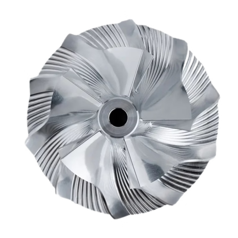
Five-axis pays off when a part has features on multiple faces, when the datum must stay fixed, or when a deep pocket needs a short tool. Impellers, engine housings, medical instrument bodies, and robot joints are typical. So are one-piece designs that replace an assembly of three or four bolted plates.
It does not pay off on simple prismatic parts. A plate with holes on one face and a slot on the other is faster and cheaper on a 3-axis mill with a flip fixture. The programming hours and the machine rate on a 5-axis cell are higher, and no amount of tilting will recover that.
Size matters too. On a large trunnion, the rotary table carries the part mass plus the fixture. If the combined load is close to the table rating, the servo will lag on acceleration, and the finish will show it. Keep the load under roughly 70% of the rated capacity for finishing cuts.
Material choice affects the decision as much as geometry. Aluminum 6061 and 7075 cut fast with high surface speed. Stainless 17-4PH and 316L need lower speed and more rigid setups. Titanium TC4 and Inconel need coolant through the tool and a conservative stepover.
- 1Good fitMulti-face features, tight true position, deep cavities, monolithic redesigns.
- 2Poor fitFlat plates, simple brackets, parts with one critical face.
- 3Watch the table loadHeavy fixtures eat the acceleration margin on finishing passes.
Mistakes that scrap parts on a 5-axis machine
The most common failure is a stale pivot offset. Machines drift after a crash or a service visit, and the offset in the parameters no longer matches the physical geometry. The symptom is a part that measures fine in one orientation and off in another.
The second is a mismatched post-processor. If the post was written for a different machine model, the rotary direction or the pivot distance will be wrong. The simulation looks correct because it runs on the same wrong numbers. The collision happens on the real machine.
The third is insufficient workholding rigidity. A trunnion table amplifies any looseness because the part is cantilevered. If the fixture rings when you tap it, it will chatter at cutting speed. Add a tailstock support or a bolt-on brace before you blame the toolpath.
Finally, thermal drift. Five-axis machines generate heat in the rotary drives and the spindle. On a long cycle, the part can move 0.01–0.03 mm. For tight work, break the cycle into stages and re-measure, or hold the shop at a stable temperature.
- 1Stale pivot offsetRe-probe after any crash, service, or thermal event.
- 2Wrong postMatch the post to the machine serial and kinematics, not to the brand.
- 3Weak fixtureCantilevered parts need support; a ringing fixture will chatter.
- 4Thermal driftRe-measure on long cycles; 0.01–0.03 mm movement is normal.
Checking the first article before the run continues
On a 5-axis job, the first article is the whole quality plan. Measure the features that tie the part to its datums, not just the easy outside dimensions. A CMM report on true position and profile tells you whether the pivot offset and the work offset are both correct.
If the profile is good but a hole pattern is shifted, the work offset is off. If the profile is tapered across a face, the pivot distance is off. If one wall is thick and the opposite wall is thin, the part moved in the fixture.
We inspect 100% of parts before shipment, with raw material checks, in-process monitoring, and a final inspection. Reports are available on request. That routine catches the drift before a full batch is finished, not after.
For parts held to ±0.005 mm, use a temperature-controlled inspection room and let the part soak before measuring. A part that is 10 °C warmer than the gauge will read differently by roughly 0.002 mm over 100 mm in aluminum.
- 1Profile good, holes shiftedWork offset error; re-probe the part datum.
- 2Face taperedPivot distance error; re-check the rotary parameters.
- 3Walls unevenPart moved; check clamping torque and fixture seating.
How to operate a 5 axis CNC machine, step by step
Follow the order. Skipping a step moves the error downstream where it is harder to find.
- 11. Warm up the rotary axesRun a 20–30 minute warm-up cycle that sweeps A and B through their full travel at low feed. Thermal growth in the rotary housing moves the pivot center by a few microns. Warm-up first, then measure.
- 22. Verify pivot offsetsIndicate a known test bar or a calibrated sphere and check the pivot distance in the controller parameters. Re-probe if the deviation exceeds 0.01 mm. This one number controls all simultaneous motion accuracy.
- 33. Clean and seat the fixtureStone the table and the fixture base, then torque the clamps in a cross pattern. A chip under the fixture tilts the whole part. On a 5-axis trunnion, a 0.05 mm chip at the corner becomes a 0.2 mm error at the far edge.
- 44. Establish the work offsetProbe the part in the rotary center, not in machine coordinates. Set G54 to the pivot center and store the part offset as a separate shift. Use a probe cycle with a 0.002 mm trigger repeat, and confirm with a dry run to Z0.
- 55. Load the matched post and simulatePost the CAM file with the post-processor built for that exact machine model. Simulate the full toolpath with stock and fixture models. Look for rotary over-travel, cable wrap, and tool-holder collision before you press cycle start.
- 66. Air-cut in single blockRun the first article in air at 100% rapid override off, then step through in single block. Watch the rotary direction and the tool tip position at each reorientation. Feed at 50% for the first real cut.
- 77. Measure the first article and adjustCheck the critical features against the drawing. If a wall is tapered, correct the pivot offset. If a hole is off in true position, correct the work offset. Do not chase dimensions with cutter compensation unless the geometry is confirmed.
3-axis and 5-axis operation side by side
Use this to decide whether a job belongs on the 5-axis cell or stays on a 3-axis machine.
| Factor | 3-axis operation | 5-axis operation |
|---|---|---|
| Setups per part | 3 to 5 flips | 1 clamping |
| Datum error stack | Adds at every flip | Set once at pivot center |
| Reach for deep pockets | Long tool, more chatter | Tilt to a short tool |
| Programming hours | Lower | Higher, needs post and simulation |
| Typical tolerance | ±0.01 mm | ±0.005 mm |
| Best for | Prismatic, single-face parts | Multi-face, contoured parts |
| Fixture cost | Simple vises | Trunnion or tombstone |
Questions engineers ask about 5-axis operation
How long does it take to learn to operate a 5-axis CNC machine?
A machinist who already runs 3-axis work can learn the mechanical setup in a few weeks: work offset, probing, and first-article checks.
Programming simultaneous motion takes longer, typically several months of supervised work. The hard part is not the controller, it is understanding how the rotary axes change the tool engagement.
Do you need a special post-processor for every 5-axis machine?
Yes. The post must match the machine kinematics, the rotary configuration, and the controller model. Two machines from the same brand can have different pivot distances and different rotary limits.
A generic post will simulate fine and then over-travel or collide on the real machine, because the simulation uses the same wrong offsets.
What tolerance can a 5-axis machine hold in normal production?
On a well-maintained machine with a stable setup, ±0.005 mm is realistic for critical features, with surface finish around Ra 0.8–1.6 μm.
Tighter finish, down to Ra 0.2–0.8 μm, is possible with a dedicated finishing pass and a rigid setup. It costs cycle time.
When should a job stay on a 3-axis machine?
When the part is prismatic, when only one or two faces carry critical features, and when a flip fixture can hold the tolerance.
Moving that job to a 5-axis cell adds programming hours and machine rate without removing enough setups to pay for it.
How do you handle confidential parts and drawings?
Uploads are secure and confidential, and we sign an NDA on request before any file is reviewed.
We hold ISO 27001:2022 for information security, alongside ISO 9001:2015, IATF 16949:2016, and ISO 13485:2016 for the relevant product lines.
Send the drawing, get a process review
We quote and return a free DFM analysis within 12 hours, and production can start within 24 hours. No minimum order quantity, from one prototype to 10,000+ parts.
12-hour quote100% inspection±0.005 mmNDA on request
More from GreatLight
We publish setup notes, tooling trials and inspection data from the factory floor.











