
Lattice Structure in 3D Printing
A lattice structure in 3D printing replaces solid material with a repeating cell network, so a part can be stiff where it matters and empty where it does not. This page covers how the cells work, what wall and strut sizes actually print, and when a lattice is the wrong choice for your part.
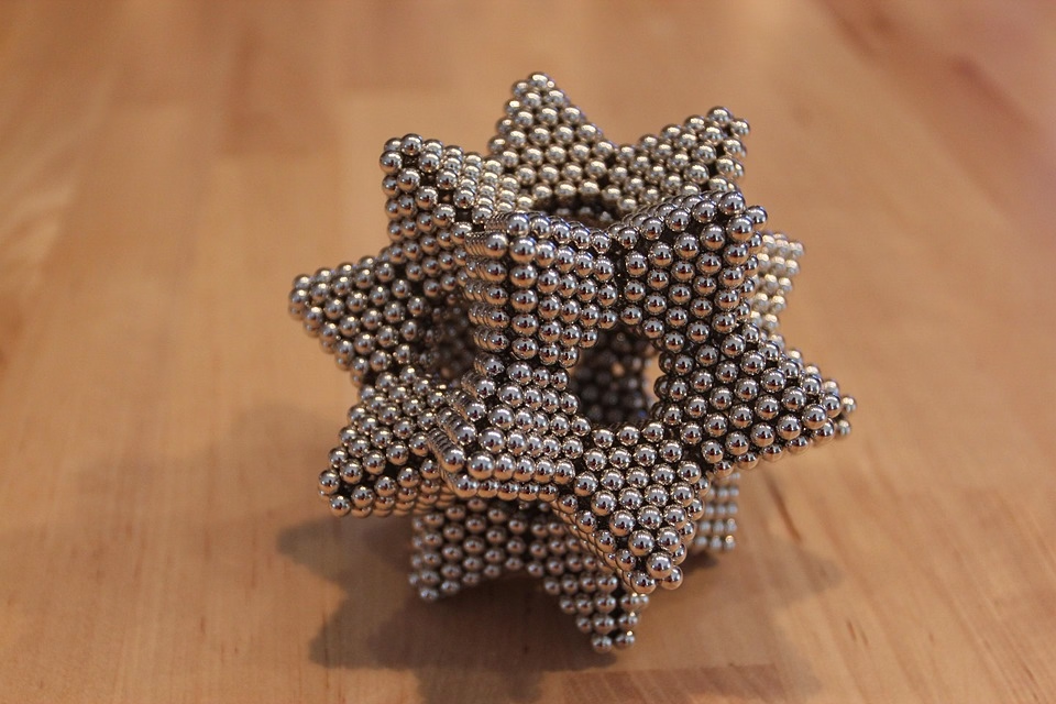
What a lattice actually does to load
A solid block carries load through its whole cross section. A lattice carries the same load through a small number of struts or thin walls, so each member sees a much higher local stress. That is the trade. You give up raw section area and get back stiffness per unit mass, plus internal space for airflow, bone ingrowth, or damping.
Stiffness of a strut lattice scales roughly with relative density squared for bending-dominated cells and closer to linear for stretch-dominated cells. A 20% dense bending lattice can lose 90% or more of the solid stiffness. Engineers who expect a honeycomb to behave like a solid block are usually disappointed by the first test.
The cell type decides which way that stiffness goes. A stretch-dominated cell such as an octet truss puts its members mostly in tension and compression, so it holds stiffness well at low density. A bending-dominated cell such as a simple cube or a Kelvin foam bends its struts instead, which is softer but absorbs more energy before it fails.
Both are useful. Pick the cell from the load path, not from the render. If the part is a bracket that must not deflect, you want stretch-dominated geometry and a load path that lines up with the struts. If the part is a helmet liner or a damper, bending-dominated cells are the point.
Strut, wall, and cell size limits that decide printability
Every additive process can only hold a minimum feature. On a laser powder bed system, a strut thinner than about 0.3 mm tends to come out porous or broken, because the melt pool is wider than the strut itself. On material extrusion, a wall under two extrusion widths leaves gaps between roads. These numbers move with the machine, but the rule does not: the smallest strut in the file must be larger than the smallest feature the process can fuse.
The usual working range for metal powder bed is a 0.3-0.5 mm strut with a 0.8-1.2 mm cell opening. That keeps the powder removable and the struts solid. Below that, you get partially fused struts, trapped powder, and a part that looks right on the build plate and fails in the vice.
Cell aspect ratio matters as much as cell size. A cell that is 4 mm tall and 1 mm wide overhangs on its own struts, so the printer needs support inside the lattice. Support inside a lattice is nearly impossible to remove. Keep the cell close to cubic, or rotate the whole lattice so the struts sit within about 45 degrees of vertical.
Aspect ratio also drives anisotropy. A tall, narrow cell is stiff along the tall axis and soft in the other two. If the load is multiaxial, use a near-cubic cell and accept the higher mass, or grade the lattice so density rises where the stress does.
Build orientation and trapped powder
Orientation changes both the surface finish on the struts and the self-supporting behavior of the cell. Struts built at a shallow angle to the build plate sit on their own lower surface and need no support. Struts closer to horizontal need support or a larger strut diameter to survive. A 45 degree rule of thumb is a reasonable starting point for most metal powder bed work.
For a lattice structure in 3D printing, the harder problem is often powder removal, not printing. A closed cell traps powder that you cannot reach with a brush, and loose powder inside a sealed volume will rattle out later. Open the cell faces, add drain holes at the lowest point of each cavity, and plan the escape path before the build, not after.
Heat treatment and stress relief come next. Thin struts cool faster than thick sections, so a lattice with a graded density can warp at the boundary between dense and sparse regions. A stress relief cycle before any machining step keeps the geometry where the model put it.
If the lattice sits inside a housing that will later be machined, leave stock on the machined faces. Do not try to hold tolerance on a lattice face directly. Turn the lattice surfaces into non-critical faces and put the datums on solid material.
When a lattice beats a solid part, and when it does not
A lattice wins when mass is the design driver and the load path is known. Aerospace brackets, drone arms, heat exchanger cores, surgical implants, and robotic end effectors are common fits. It also wins when you need internal surface area, such as a heat sink or a filter, or when you want controlled crush behavior in an energy absorber.
A lattice loses when the part is a bearing seat, a sealing face, or a thread. Those features need full density and a machined surface. A lattice also loses when the part is small and simple. If a 40 mm bracket can be milled from solid aluminium in one setup at ±0.005 mm, adding a lattice only adds cost and inspection work.
Cost is the other filter. A lattice takes longer to slice, longer to build, and longer to clean. On a metal machine, build time is often the largest line item. A 25% mass reduction that doubles build time is a bad trade unless the mass reduction is the whole reason the part exists.
The practical test: does the part have a stiffness or weight requirement that a solid machined version cannot meet? If yes, model the lattice. If no, keep it solid and spend the effort on tolerance and finish instead.
How to check a lattice before you commit to a build
Slice the model and inspect the struts in the preview, not in the CAD. Many lattice failures are visible only in the toolpath: a strut that thins to nothing at a cell junction, a wall that the slicer drops because it is under the minimum width, or a support volume that the software places inside a cell you cannot reach.
Run a quick section cut through the densest region and the thinnest strut. Measure the actual strut diameter in the sliced file. If the minimum strut is under 0.3 mm in metal, thicken it or reduce the cell count. It is cheaper to change a parameter than to scrap a build.
For load-bearing lattices, print a small coupon of the same cell and the same orientation, then test it. Coupon testing catches the gap between the nominal strut diameter and the as-built strut diameter, which can run 0.05-0.1 mm in either direction on a metal machine.
Inspection after the build should include the lattice itself, not just the solid faces. Visual check for broken struts, mass check against the model, and a dimensional check on the solid datums. Reports are available on request for production runs.
If the part is going into a regulated program, involve quality early. The lattice geometry should be on the drawing as a controlled feature with a defined cell type, cell size, and strut range, so the shop and the inspector are reading the same specification.
Lattice type and process fit
Use this to narrow the choice before modeling.
| Lattice type | Best for | Typical strut or wall | Watch out for |
|---|---|---|---|
| Octet truss | Stiffness-critical brackets | 0.4-0.8 mm strut | Hard to remove powder |
| Body-centered cubic | General lightening | 0.5-1.0 mm strut | Soft in shear |
| Kelvin foam | Energy absorption | 0.3-0.6 mm strut | Low stiffness per mass |
| Gyroid surface | Heat exchange, implants | 0.3-0.5 mm wall | Slicer support inside cells |
| Honeycomb | Flat panels, in-plane load | 0.5-1.0 mm wall | Weak out of plane |
| Simple cubic | Fast models, low load | 0.6-1.2 mm strut | Bends, not stretches |
The short answer
Model a lattice when mass or internal surface area is the driving requirement and the load path is defined. Keep the part solid when it needs a machined datum, a seal, or a thread, or when a milled solid already meets the spec.
Lattice questions we get from engineers
Can you machine a lattice after printing?
Only the solid faces. A cutting tool cannot follow a 0.4 mm strut without pushing it out of position, and the tool pressure will bend or break the cell. We machine the datums, bores, and sealing faces on solid material and leave the lattice as-printed.
If a lattice face needs a flat surface, add a solid rim or skin to the model, machine that rim, and let the lattice sit behind it.
What minimum strut diameter can you hold?
It depends on the process. Metal powder bed handles 0.3-0.5 mm struts reliably when the cell is open and the powder can escape. Below 0.3 mm, struts come out porous and the yield drops fast.
For plastic processes, the limit is set by the nozzle or laser spot. A 0.4 mm nozzle cannot lay a 0.3 mm wall without gaps.
Does a lattice always reduce weight?
No. A lattice reduces solid volume, but the printed part also needs a skin, a rim, and often a solid mounting pad. On small parts, those solid features can eat most of the savings.
The real comparison is the finished part mass, not the mass of the lattice region alone. We check the whole model before quoting.
How do you quote a lattice part?
Send the model and tell us the cell type, cell size, and strut range, or the load case if the lattice is not designed yet. We review the geometry against the process limits and come back with a quotation and a short DFM note within 12 hours.
Uploads are secure and confidential. An NDA is available on request.
Can a lattice part be inspected dimensionally?
The solid features can be measured to ±0.005 mm on our equipment. The lattice itself is checked by mass, by visual inspection for broken struts, and by coupon testing when the part is load-bearing.
We define the lattice on the drawing as a controlled feature so the specification is unambiguous. Reports are available on request.
Which industries use lattice parts most?
Aerospace and medical are the two heaviest users, because mass and internal surface area both matter there. Automotive and EV use lattices in structural and thermal parts, and robotics uses them in arms and end effectors where inertia limits speed.
We also see lattices in new energy hardware, mostly for thermal management.
Send us your lattice model
Upload the CAD file and tell us the load case. We review the geometry against process limits and return a quotation with a DFM note within 12 hours.
12-hour quoteNo minimum order quantity100% inspection
More from the shop floor
We publish setup notes, tooling trials and inspection data from the factory floor.











