
Metal 3D Printing and CNC: How to Choose the Right Process
This page explains how metal 3D printing and CNC machining each build a part, where their limits sit, and which one fits your geometry, tolerance, and lot size. It is written for design and manufacturing engineers who need a decision, not a slogan.
In this article
- 1
- 2
- 3
- 4
- 5
- 6
- 7
- 8
Key takeaways
How each process actually forms metal
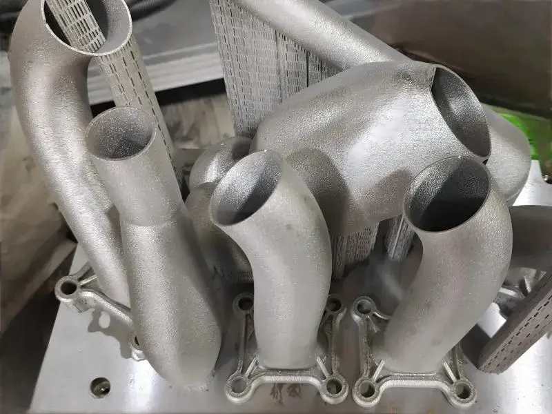
Metal 3D printing builds a part by adding material. A laser or electron beam melts fine powder, layer by layer, following a sliced CAD model. Each layer is typically 20–60 μm thick. The melt pool solidifies in milliseconds, so the grain structure is fine and directional. Support structures anchor overhangs and pull heat out of the part. Those supports are cut off later, and the surfaces they touch usually need finishing.
CNC machining starts with solid stock and removes material with a rotating cutter. A 3-axis machine moves the tool in X, Y, and Z. A 5-axis machine tilts the tool or the table, so it can reach five faces in one setup. The cutter leaves a controlled surface, and the part keeps the properties of the wrought or cast billet it came from. There is no melting step in the final shape.
The engineering consequence is simple. Additive creates geometry that subtractive tools cannot reach. Subtractive creates surfaces and tolerances that additive cannot hold without help. Neither process is a replacement for the other on a typical metal part.
- 1AdditiveMelt powder in layers. Complex internal geometry, near-net shape.
- 2SubtractiveCut solid stock. Tight tolerance, known material properties.
- 3HybridPrint near-net, then machine the critical faces and bores.
What geometry each process can and cannot make
Additive shines where the part has internal channels, lattice cores, or organic ribs. A conformal cooling channel that curves through a mold insert is a classic case. So is a bracket that is 40 percent lighter because the load path is a lattice instead of solid metal. These shapes are possible because the tool never has to enter the part.
CNC shines where the part has flat faces, precise bores, threads, and sealing surfaces. A hydraulic manifold with a flat gasket face and a Ø12 H7 bore is a machining job. So is a shaft with a bearing seat and a keyway. The cutter reaches the surface directly, so the dimension is a direct result of machine motion, not of thermal shrinkage.
The limits run in both directions. Additive struggles with large flat surfaces, sharp internal corners, and unsupported overhangs beyond roughly 45 degrees. CNC struggles with deep internal cavities, cross-drilled channels that meet at odd angles, and features hidden behind other features. If your part has both, plan a hybrid route from the start.
- 1Good for printingConformal channels, lattices, organic ribs, small batch complex shapes.
- 2Good for machiningBores, threads, flat seals, keyways, tight true position.
- 3Avoid in printingLarge flat faces, sharp internal corners, steep unsupported overhangs.
- 4Avoid in machiningLong curved internal channels, deep cavities with no tool access.
Tolerance, surface finish, and what printing leaves behind
As-built metal printing typically lands in the ±0.1 mm range on a good day, and worse on tall or thin parts. The melt pool and the thermal gradient move the part as it grows. Downskin surfaces, the ones facing the build plate, are rougher than upskin surfaces. Expect Ra 8–15 μm as-built on many alloys. That is far from a sealing face.
CNC machining holds ±0.005 mm on a well-fixtured part. Surface finish runs from Ra 1.6–3.2 μm as machined, down to Ra 0.8–1.6 μm with a finishing pass, and Ra 0.2–0.8 μm after polishing. The number you get depends on the setup, the tool, and the material, not on the process alone.
So the practical rule is this. If a face must seal, locate, or slide, machine it. If a surface is cosmetic or non-critical, printing may be acceptable as-built. Many production parts are printed to near-net shape and then machined only on the functional surfaces. That keeps the additive advantage for the geometry and the machining advantage for the interface.
- 1As-built printingAbout ±0.1 mm, Ra 8–15 μm on downskin surfaces.
- 2CNC as machined±0.005 mm, Ra 1.6–3.2 μm typical.
- 3CNC fine finishRa 0.2–0.8 μm after polishing when the drawing calls for it.
Material behavior: powder alloys versus wrought stock
Machined parts inherit the properties of the stock. A 7075-T6 billet is already heat treated and stress relieved before the cutter touches it. A 17-4PH bar is consistent from one lot to the next. The machinist knows what the material will do, and the inspection report reflects that.
Printed parts inherit the properties of the melt. Residual stress builds up as layers cool at different rates. Some alloys need stress relief before the part is cut off the plate, or it will warp. Porosity can appear if the laser power, scan speed, and layer thickness are not matched. Titanium and Inconel print well and are common choices. Aluminum alloys are harder because they reflect the laser and conduct heat away quickly.
For both processes, the material menu overlaps more than people expect. Aluminum, stainless steel, steel, copper, brass, titanium, and Inconel are all available. The difference is not which metals exist. It is which ones give you a predictable result on the first try. If the part is safety-critical, ask for the material certificate and the inspection data, whichever process you pick.
- 1Wrought stockKnown grain, known heat treat, consistent lot to lot.
- 2Printed alloyFine directional grain, residual stress, needs stress relief.
- 3Hard to printAluminum alloys reflect the laser and conduct heat away fast.
- 4Easy to printTitanium and Inconel are common and well understood.
Cost drivers and lead time in practice
Printing cost tracks build volume and machine time, not part complexity. Two parts with the same bounding box cost about the same to print, even if one has ten times the internal detail. That is why printing looks expensive for a simple block and reasonable for a complex one. Powder cost, support removal, and heat treat add to the total.
CNC cost tracks setup count and cycle time. A part that needs three setups costs more than one that needs one. A part with a 40-minute cycle costs more than one with a 4-minute cycle. Complex geometry raises the setup count and the risk of a mistake, so machining rewards designs that can be reached in fewer orientations.
In our shop, a quotation and free DFM analysis come back within 12 hours, and production can start within 24 hours. Parts ship in 3–5 days. There is no minimum order quantity, so a single prototype and a 10,000-part run both fit the same workflow. Those numbers apply to the processes we run, not to every shop or every geometry.
- 1Print cost driverBuild volume and machine time, not detail count.
- 2CNC cost driverSetup count and cycle time, not part size alone.
- 3BothInspection and post-processing are real line items.
The hybrid route: print near-net, then machine
Most production parts that use additive geometry also get machining. The printer makes the near-net shape with the internal channels and the weight-saving lattice. The mill then cuts the mounting faces, the bores, and the threads. This is not a compromise. It is the standard route for complex metal parts that also have to bolt to something.
The design rule is to leave machining stock on every surface that will be cut. A common allowance is 0.5–1.0 mm per face. Put the datum features on the printed part in a place the machinist can reach with a probe or an edge finder. If the datums are on a rough printed surface, the first cut is a guess and every later cut inherits the error.
Plan the sequence early. Printing, stress relief, support removal, then machining. Skip the stress relief and the part may move after the first cut, which shows up as a bore that is round on the machine and oval on the bench. Talk to the shop before you freeze the model. A five-minute change in CAD is cheaper than a scrapped build.
- 1Leave stock0.5–1.0 mm per machined face is a common starting point.
- 2DatumsPlace them where the machinist can reach them.
- 3SequencePrint, stress relief, support removal, then machine.
Metal 3D printing and CNC: side-by-side comparison
Use this when the part could go either way.
| Factor | Metal 3D printing | CNC machining | Pick this when |
|---|---|---|---|
| Geometry freedom | Internal channels, lattices | Reachable surfaces only | Channels needed: print |
| As-built tolerance | About ±0.1 mm | ±0.005 mm | Tight fit: CNC |
| Surface finish | Ra 8–15 μm as-built | Ra 0.2–3.2 μm | Seal face: CNC |
| Tooling | None | Fixtures and cutters | Design still changing: print |
| Lot size fit | One to a few hundred | One to 10,000+ | High volume: CNC |
| Material choice | Focused alloy set | Wide stock menu | Exotic stock: CNC |
| Post-processing | Support removal, stress relief | Deburr, finish, plate | Both need a plan |
| Best use | Near-net complex shape | Finished functional part | Often both in one route |
The short answer
If the part is defined by internal channels or a lattice, print it. If it is defined by a bore, a thread, or a sealing face, machine it. If it has both, print near-net and machine the interfaces.
Frequently asked questions
Can a printed metal part hold the same tolerance as a machined part?
Not as-built. A typical metal print lands around ±0.1 mm, and tall or thin sections can drift more as the part cools.
If the drawing calls for ±0.005 mm, the critical faces have to be machined after printing. That is normal for production parts.
Is CNC machining always faster than metal 3D printing?
Not for the first part. A complex printed geometry can be built in one setup with no tooling, while the same shape might need several fixtures and long cycle times to machine.
For a simple part at quantity, CNC is usually faster because the cycle repeats without build setup between parts.
Which metals can be printed and machined at the same shop?
The overlap is wider than most people assume. Aluminum, stainless steel, carbon steel, copper, brass, titanium, and Inconel appear on both sides of the shop.
The difference is predictability. Wrought stock behaves the same from lot to lot, while printed metal needs the right laser parameters and a stress relief step to stay stable.
Do printed parts need support structures?
Yes, wherever an overhang faces the build plate. Supports carry heat away and hold the geometry in place while it forms.
They are cut off after the build, and the surfaces underneath are usually rougher. If that surface must seal or locate, add a machining allowance there.
How do I decide between the two for a bracket?
Look at the load path and the interfaces. If the bracket only bolts to flat surfaces and carries a simple load, CNC is usually the cheaper and more predictable route.
If the bracket needs to be much lighter, or the load path calls for an organic rib pattern, printing becomes competitive. Many brackets end up printed near-net with machined bolt pads.
What information should be on the drawing?
Datum features, critical dimensions with tolerance, surface finish callouts, and the material specification. Mark which faces are functional and which are cosmetic.
That lets the shop decide where to leave stock, where to print as-built, and how to sequence the operations. It also keeps the quote accurate.
Send the model and get a process recommendation
Upload your CAD file and we will return a quote plus a free DFM review within 12 hours, including which faces should be printed and which should be machined.
12-hour quote100% inspectionNo MOQNDA on request
More process notes
We publish setup notes, tooling trials and inspection data from the factory floor.











