
Operating Table Rail Mounts Die Casting: How the Process Works
Rail mounts clamp armrests, leg supports, screens, and trays onto the side rails of a surgical table. This page explains how operating table rail mounts die casting actually behaves as a process, where the casting stops and machining starts, and which part geometries should never be quoted as a casting. Written for design engineers and sourcing engineers who have to sign off on the drawing.
In this article
- 1
- 2
- 3
- 4
- 5
- 6
- 7
Key takeaways
Why die casting fits the rail mount body
A surgical table rail mount is a small structural bracket with one job: hold an accessory firmly against a 25 × 10 mm or 30 × 10 mm side rail, then release it cleanly when the nurse pulls the lever. That means a clamped jaw, a pivot or slide, a locking mechanism, and mounting holes, all inside a part that is often no larger than a hand. The geometry is repetitive, the walls are thin, and the annual volume on a successful table platform runs into thousands.
High-pressure die casting suits that profile. Molten aluminium or zinc is injected into a hardened steel die at high velocity, and the cavity fills in milliseconds. You get near-net shape with wall sections of 2.5 to 4 mm, integrated ribs, draft on every vertical face, and ejector pin marks on the non-cosmetic side. Cycle time is short and the per-part cost drops sharply once the tool is paid for.
What the process does not give you is a finished functional surface. As-cast tolerances on a part this size typically sit around ±0.1 mm on a good day, and the die itself wears over its life. Add parting line mismatch, ejector witness marks and a small amount of warpage, and you have a part that looks right but will not clamp repeatably. The rail interface is where that shows up first.
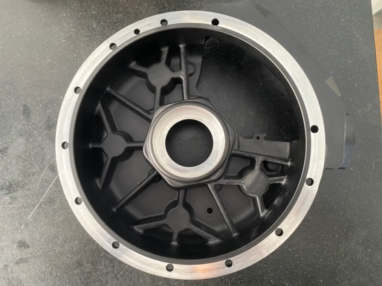
So the working model is simple: casting creates the 80 percent of the part that is shape, and CNC machining creates the 20 percent that is function. On operating table rail mounts die casting projects, we usually plan the casting with 0.3–0.5 mm of stock on every face that will be cut, then machine the jaw, the bore, the datum face and the locking teeth in one or two setups. Everything else stays as cast.
- 1As castNear-net body, ribs, bosses, cosmetic surfaces, non-critical holes.
- 2Machined after castingRail jaw faces, pivot bore, mounting datum, locking teeth, thread bosses.
Alloy choice for rail mounts: aluminium, zinc or magnesium
Aluminium is the default for rail mounts that carry load. ADC12 (close to A383) fills thin sections well, machines acceptably and takes anodizing, powder coating or electroless nickel. A360 offers better corrosion resistance and slightly better ductility, which matters on a part that gets clamped and released hundreds of times. If the mount is a structural arm rather than a small clamp, a higher-silicon or modified alloy with more elongation is worth the conversation with the caster.
Zinc alloys such as Zamak 3 and Zamak 5 are worth considering when the part is small, the walls are very thin, and the priority is dimensional stability straight out of the die. Zinc casts to tighter as-cast tolerance than aluminium, needs no draft-heavy redesign, and takes plating well. The trade-off is weight. A zinc rail mount on a heavy accessory arm adds mass the nurse has to lift.
Magnesium alloys like AZ91D cut weight by roughly a third against aluminium, and they die cast well. The reason they are rare in operating rooms is not mechanical. Magnesium dust and fines carry a fire risk during machining and finishing, so the shop needs dedicated handling. For most rail mount programs, ADC12 or A360 is the practical answer, and the weight saving comes from rib design instead of alloy.
One metallurgical point that comes up in audits: die castings contain gas porosity from the injection process. That porosity is not a defect by itself, but it limits what you can do later. A gas-filled casting cannot be welded and re-machined without blistering, and it will not survive a high-temperature heat treatment. If the drawing calls for T6, the part is not a die casting. It is a gravity casting or a machined part.
- 1ADC12General rail mount bodies. Good fill, easy finishing, lowest cost.
- 2A360Better corrosion resistance for repeated wipe-down and chemical exposure.
- 3Zamak 3 / 5Small clamps, thin walls, tight as-cast tolerance, higher weight.
Wall thickness, ribs and draft: the rules that decide yield
The single biggest driver of die casting yield on a rail mount is wall thickness uniformity. Metal shrinks as it solidifies, and thick regions solidify last. If a 6 mm boss sits next to a 2.5 mm wall, the boss pulls metal from the wall while it cools, and the part warps. On a rail mount, warpage shows up as a rail gap that tapers along its length, which means the clamp grips at one end and slips at the other.
The fix is not to thicken everything. It is to keep nominal walls in the 2.5–4 mm range and core out thick sections. A locking boss that needs 8 mm of thread depth should be a cored hole with a 3 mm wall, not a solid pillar. Ribs work the same way: 1.5–2 mm thick, with a height no more than three times the thickness, and a draft of at least 1° per side so the part ejects without dragging.
Draft matters more than most CAD models suggest. Every vertical face that runs in the direction of die pull needs 1° to 2° of draft, and textured or bead-blasted surfaces need 2° to 3° because the texture itself creates drag. A rail jaw designed with 0.5° draft will gall, and the galling marks land exactly on the clamping surface.
Fillet radii are the other quiet failure point. Sharp internal corners concentrate stress and restrict metal flow, so the cavity may not fill before the metal freezes. We ask for a minimum 1 mm internal fillet, 2 mm on load-bearing corners, and a fillet at the base of every rib. Those radii also reduce cracking at the jaw root during repeated clamping cycles.
- 1Nominal wall2.5–4 mm. Above 5 mm, core it out.
- 2Ribs1.5–2 mm thick, height ≤ 3× thickness, 1° draft minimum.
- 3Internal fillets1 mm minimum, 2 mm on load paths and rib roots.
- 4Draft1–2° plain surfaces, 2–3° textured surfaces.
The rail interface: where casting meets the surgical table
The rail interface is the only part of the mount that touches the table, and it is the part that determines whether the accessory feels solid or loose. Surgical side rails are not precision ground surfaces. They are extruded or machined profiles with a tolerance band of their own, and they wear. A clamp designed for a nominal 30 mm rail has to work on a 30.2 mm rail without binding and on a 29.8 mm rail without slipping.
That requirement pushes the design toward a compliant jaw rather than a rigid one. A rigid cast jaw machined to a tight gap will grip a nominal rail and rattle on a worn one. A jaw with a slight elastic section, or a separate machined insert, absorbs the variation. The insert approach costs one more part number but lets you control the grip surface separately from the casting, which is usually the better trade on a high-volume platform.
Locking teeth and detents follow the same logic. As-cast teeth are not sharp enough or consistent enough to index repeatably, so the tooth profile is normally machined after casting. On a 5-axis machine the whole tooth band can be cut in one pass with a small end mill, which keeps the pitch consistent around the arc. If the teeth are cast only, expect indexing error and visible wear within the first year of clinical use.
Bushing bores for the pivot pin are the tightest feature on the part. A typical requirement is a bore that holds a stainless pin without perceptible play, which lands in the ±0.005 mm to ±0.02 mm range depending on the pin fit. That is a machining operation, not a casting operation. We plan the casting with a 2–3 mm undersized bore and bore it to size after the casting has fully stabilized.
- 1Rail gapDesign for the tolerance band of the rail, not the nominal size.
- 2Grip surfaceMachined insert or machined cast face. Never as-cast only.
- 3Pivot boreLeave 2–3 mm stock, bore after casting stabilizes.
Porosity, hygiene and sterilization: the medical boundary
Operating table accessories get wiped down with aggressive disinfectants, and some go through autoclave cycles. That environment punishes any surface that traps moisture or harbours residue. Die cast aluminium has a naturally rough as-cast skin with a thin oxide layer, and if that skin is left unfinished in a crevice, cleaning fluid sits there. The practical answer is a full finishing sequence: bead blast or tumble to remove the skin, then anodize, powder coat, or electroless nickel depending on the chemical exposure profile.
Electroless nickel is common on rail mount hardware because it deposits evenly on complex geometry, including the inside of cored holes, and it resists the alkaline cleaners used in theatres. Hardcoat anodizing gives better abrasion resistance on the jaw faces but is less tolerant of the sharp edges left by machining. Powder coating covers well and is inexpensive, but it chips at the rail contact point, so it is usually reserved for non-contact surfaces.
Porosity becomes a hygiene issue in a specific way. Surface porosity on a machined face opens small voids that hold residue. A casting with heavy porosity in the jaw region will show pits after machining, and those pits are hard to clean. This is why the casting process needs vacuum assist or squeeze pin control on the rail interface region, and why we inspect that area after machining rather than before.
Sub-surface porosity also limits how the part can be repaired. A casting with a blister at the surface cannot be welded and re-machined, because the gas expands under the weld heat. If a rail mount fails inspection, the part is scrapped. Designing with generous radii, uniform walls and a well-placed gate reduces that scrap rate, but it never reaches zero on a complex casting.
- 1Bead blast or tumbleRemoves as-cast skin before any coating.
- 2Electroless nickelEven coverage inside cored holes, good chemical resistance.
- 3Hardcoat anodizeBest wear resistance on jaw faces; needs edge control.
Die casting vs machined-from-solid vs gravity casting
Compare by volume, tolerance and geometry, not by unit price alone.
| Factor | Die casting (HPDC) | Machined from solid | Gravity casting |
|---|---|---|---|
| Typical annual volume where it wins | 3,000+ parts | 1 to 2,000 parts | 500 to 5,000 parts |
| As-produced tolerance | ±0.1 mm as cast | ±0.005 mm | ±0.3 mm as cast |
| Wall thickness capability | 2.5–4 mm uniform | Any, set by tooling | 4–8 mm practical |
| Tooling cost and lead time | High, several weeks | None | Medium, several weeks |
| Porosity level | Higher, gas entrapment | None | Lower than HPDC |
| Post-casting machining | Usually required on interfaces | Not applicable | Almost always required |
| Best fit for rail mounts | High-volume standardized clamp bodies | Prototypes and low-volume custom tables | Medium volume, thick-wall structural arms |
When to cast and when to cut
If the rail mount is a standardized clamp body running 3,000 units a year or more, cast it in ADC12 and machine the jaw, bore and teeth. If the table is a low-volume or custom platform, or the mount is a one-off structural arm, machine it from solid 6061-T6 and skip the tool entirely. Casting pays back on repetition, not on complexity.
Rail mount die casting questions engineers ask
Can a die cast rail mount hold ±0.005 mm without machining?
No. As-cast tolerance on a part this size is around ±0.1 mm on a good die, and it drifts as the die wears. The ±0.005 mm figure applies to features that are machined after casting, such as the pivot bore or a datum face.
The practical sequence is to cast with 0.3–0.5 mm of stock on any functional face, then cut it on a 5-axis or 4-axis machine. That gives you the casting's shape economics and the machining's dimensional control on the same part.
How much wall stock should I leave for post-casting machining?
For aluminium HPDC at this part size, 0.3–0.4 mm per machined face is typical, and 0.5 mm if the face is large or the die is expected to run a long life. Less than 0.2 mm risks cutting into porosity or leaving the surface unmachined where the casting drifts.
Leave more on bores. A pivot bore that will be finish-bored should start 2–3 mm undersized so the machining pass removes the full cast skin and any surface porosity.
Why does my cast rail mount warp after machining?
Warpage after machining usually means residual stress is being released, not that the machining was wrong. The casting cooled unevenly because of a thick boss or a non-uniform wall, and cutting one side unbalanced the stress.
Two fixes work. Redesign the wall thickness to be uniform and core out the thick section, or rough machine, let the part rest, then finish machine. On tight rail gaps, both are often needed.
Is zinc a better choice than aluminium for rail mounts?
Zinc casts to tighter as-cast tolerance and fills very thin walls, which helps small clamps with fine detail. It also plates easily. The problem is density, roughly 2.5 times that of aluminium.
On an accessory arm the nurse lifts and positions, that extra mass matters. Use zinc for small, stationary clamps and aluminium for anything that moves or carries a bending load.
Can a cast rail mount be welded if it fails inspection?
Generally no. HPDC parts contain entrapped gas, and welding heat expands it, causing blisters and porosity at the weld. The repair rarely holds dimension and often fails leak or cosmetic checks.
The better route is to scrap the part and correct the casting process. Gate location, vacuum assist and uniform wall design are the levers that reduce that scrap rate in the first place.
What finishing do rail mounts need for hospital cleaning?
At minimum, remove the as-cast skin by bead blasting or tumbling so no rough oxide layer remains in crevices. From there, electroless nickel covers complex geometry evenly and handles alkaline cleaners well.
Hardcoat anodizing is the choice for jaw faces that see abrasion, but the edges need control because anodize builds on sharp corners. Powder coating is fine for non-contact surfaces but chips at the rail contact point.
Send the drawing, get a DFM answer
Upload your rail mount drawing and we will return a quotation with free DFM analysis within 12 hours, including wall thickness and draft feedback before any tool is cut.
12-hour quoteFree DFM analysis100% inspection before shipmentNDA on request
More from the shop floor
We publish setup notes, tooling trials and inspection data from the factory floor.











