
01
Tolerance claimed, not measured
A shop quotes ±0.01 mm and then ships a first article at ±0.03 mm. You find out at assembly, when the bearing bore will not hold preload and every unit needs rework.
Send a CAD file and we quote it within 12 hours, with DFM notes on features that will not cut cleanly. Tight-tolerance metal and plastic parts, one piece to 10,000+.
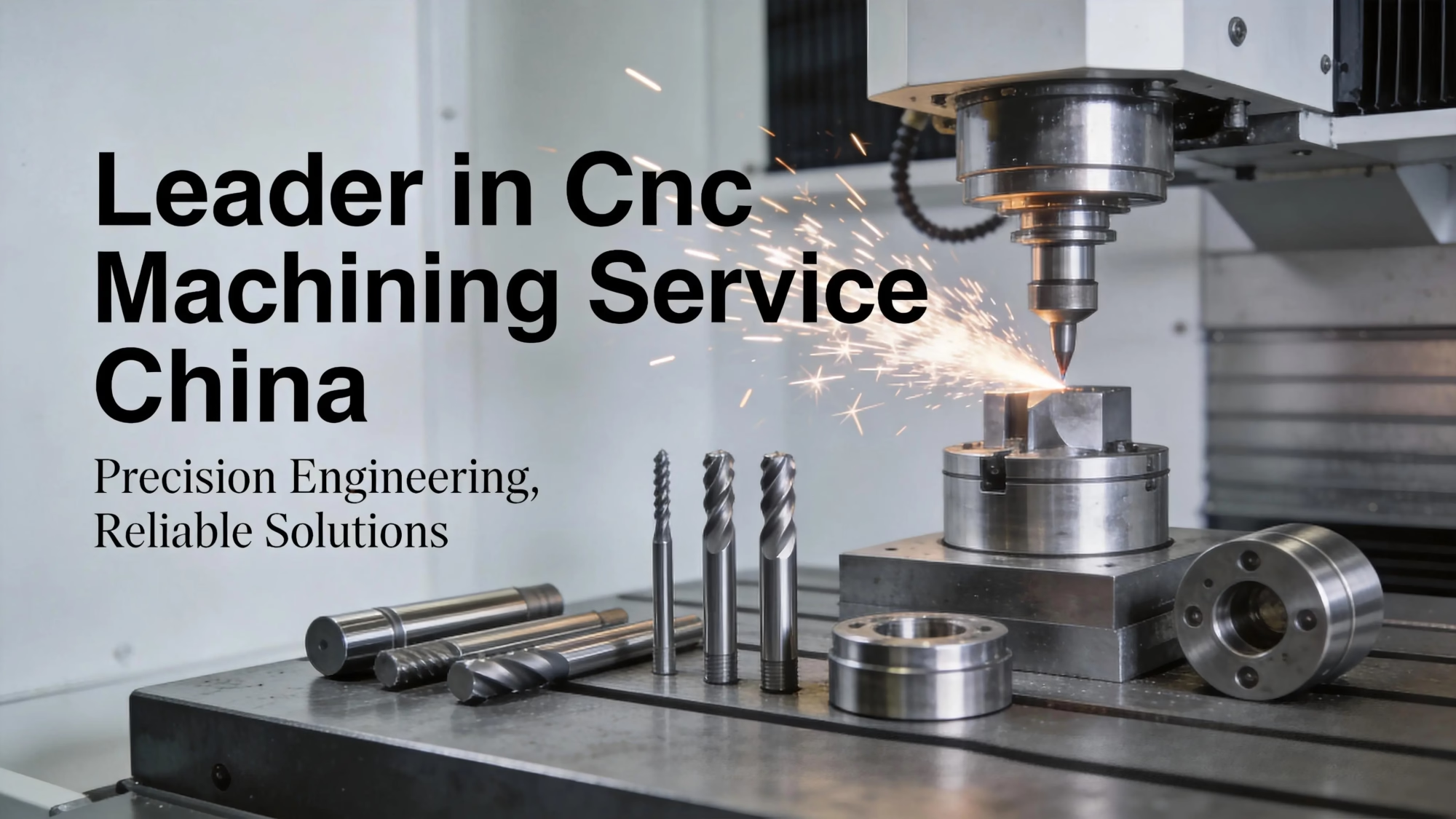
Most bad machining orders look fine on paper. They fail at the bench.
A shop quotes ±0.01 mm and then ships a first article at ±0.03 mm. You find out at assembly, when the bearing bore will not hold preload and every unit needs rework.
A 0.8 mm aluminum wall looks fine in CAD. Three days after cutting, the part warps and the flatness callout is gone. No stress relief was scheduled.
Bead blasting rounds a 0.2 mm edge. Anodizing adds 8 μm per surface and closes a press-fit bore. Nobody checked the plating build-up against the tolerance.
You get a lump-sum price and no DFM feedback. Deep pockets, a 20:1 bore and a sharp internal corner all stay in the file, so the first run is scrapped and the second one is late.
Every step has a measurement attached to it, from raw stock to the shipping box.

We quote ±0.005 mm only where the geometry and material support it. That call is made before cutting, not after. A 200 mm aluminum bracket with a thin web will not hold that number without stress relief, so the DFM note says so and we schedule the relief operation.
In-process checking runs on the machine. Operators measure critical features against the drawing at set intervals, and the readings are logged with the part number and the operation. When a dimension starts to drift inside the control band, the offset is corrected before the feature is out of tolerance. Nothing waits until final inspection to be discovered.
Final inspection covers 100% of parts before shipment. Raw material certificates are checked on receipt, in-process readings are recorded during cutting, and the final report is generated on request. For regulated programs we can supply first article inspection reports against the drawing balloon numbers.
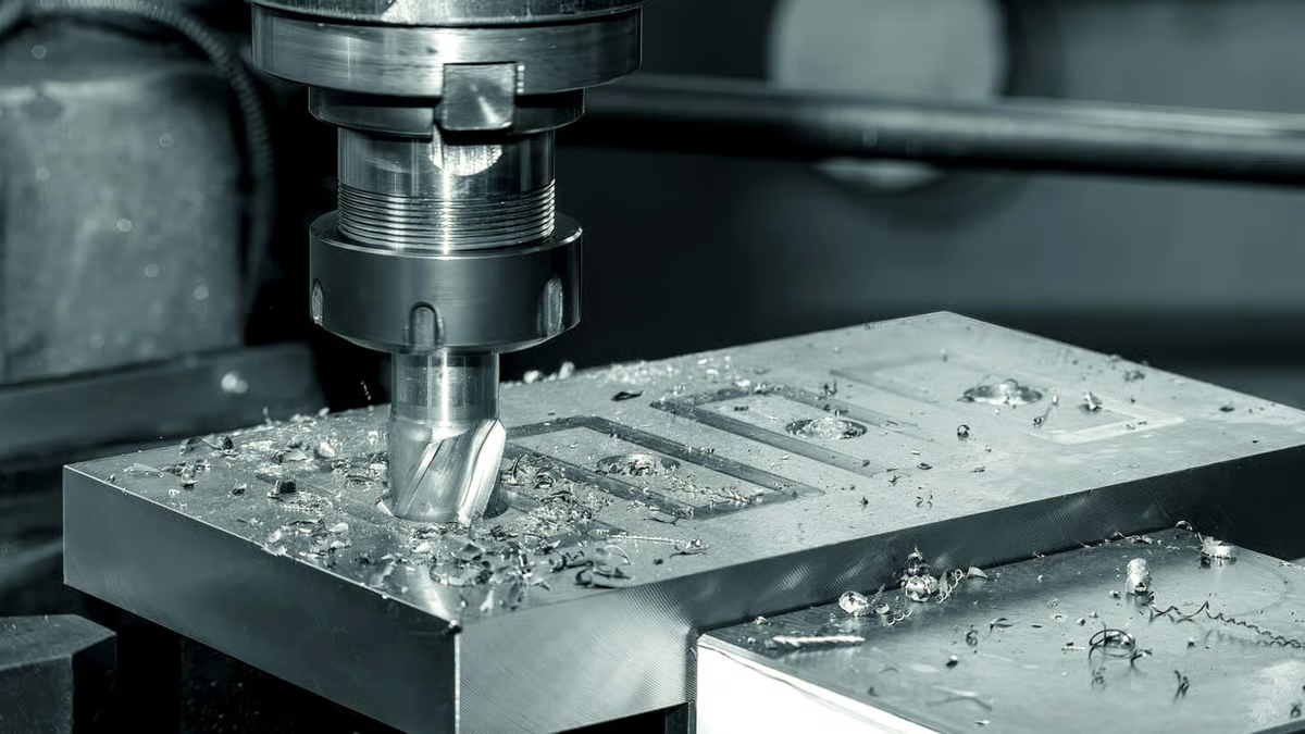
A part with features on five faces and a positional callout between them belongs on a simultaneous 5-axis center. One setup, one datum, no re-fixturing error. We run 16 of them, and they take the work where stacked tolerances would otherwise eat the budget.
Parts that are mostly turned with a few cross features go to the 16 mill-turn centers. Turning and milling finish in one cycle, so the concentricity between the bore and the bolt pattern is set by the machine, not by a second chucking.
Large work goes on machines with 4,000 mm of travel. Compact housings and manifolds run on the 500 × 500 × 450 mm and 600 × 600 × 600 mm platforms. Matching the part to the right platform keeps setup count down, and every setup you remove is a tolerance stack you no longer have to defend.
A Ø400 mm rotary table covers parts that need angular features indexed around a bore. If a feature can be reached in one orientation, we keep it in one orientation.
Use the geometry and the tolerance callout to choose.
| Part condition | Recommended route | Why |
|---|---|---|
| Features on 5 faces, tight position | Simultaneous 5-axis | One setup, one datum |
| Round part with cross holes | Mill-turn center | Concentricity held in one cycle |
| Length over 1,000 mm | Large-travel mill | 4,000 mm travel, no re-fixture |
| Wall under 1.0 mm | 3-axis plus stress relief | Controlled distortion, stable finish |
| Prototype, 1 to 5 parts | 3-axis or 4-axis | Lower setup cost per piece |
| 10,000+ parts per year | Mill-turn plus dedicated fixture | Cycle time and repeatability |
Six routes, one quote desk. Mix them in a single order if the assembly needs it.
Simultaneous 5-axis work for impellers, housings and parts with features on five faces and a positional callout between them.
Indexed rotary work for shafts, flanges and manifolds that need features around a bore without a second setup.
Prismatic parts, plates and brackets where the geometry fits two or three orientations and setup cost matters.
Milling and turning under one roof, so round and prismatic features on the same part stay in one tolerance chain.
One to five parts for fit checks and design review, quoted from the same file as the production run.
Anodizing, plating, powder coating, blasting and laser marking, with build-up checked against the tolerance.
Numbers you can design against.
| Item | Range | Notes |
|---|---|---|
| Achievable tolerance | ±0.005 mm | Where geometry and material allow |
| Surface finish | Ra 0.2–3.2 μm | Specify per surface |
| Maximum part size | 4,000 mm | Long-travel platforms |
| Materials | Aluminum, stainless, steel, copper, titanium, plastics | Grades listed at quote |
| Order quantity | 1 to 10,000+ parts | No minimum order quantity |
| Quote turnaround | 12 hours | With free DFM analysis |
Facts about the shop, not adjectives about the shop.
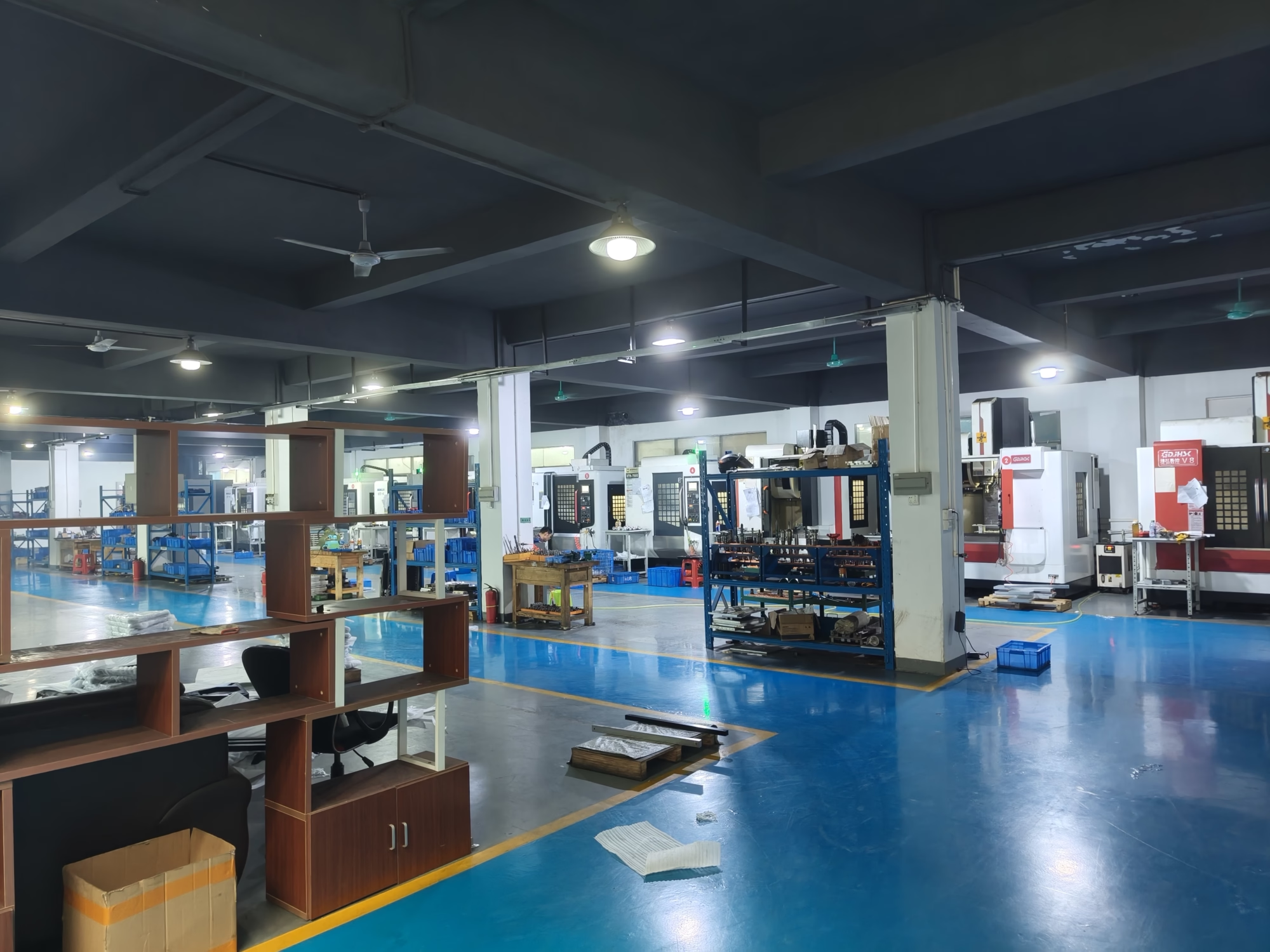
Fifteen years of production work, three wholly-owned plants and 150 technicians in Dongguan and Singapore.
In-process readings recorded per operation, with final reports on request.
Send the CAD file and the drawing. You get a price and notes on the features that will fight you.
Parts that pass inspection on the first pass, across 127 machines.
One prototype or a 10,000-part run, same quote desk, same inspection standard.
No sampling on the final gate. Every part is checked and packed with the report.
Thin webs and tight position calls need stress control and one-datum setups.
Volume programs need repeatability across runs and traceable inspection records.

Stainless components need clean finishes and documented process control.
Joint housings and end-effector plates need bores and bolt patterns in one setup.
STEP and IGES cover most parts. Send native SolidWorks or Parasolid if you have them. For sheet metal and profiles, DXF plus a PDF drawing with the tolerance block is enough.
The 3D model sets the geometry and the drawing sets the tolerance, finish and material callouts. If the two disagree, we flag it in the DFM notes rather than picking one silently.
±0.005 mm is the floor on features where the geometry supports it. That means a rigid part, a stable material and a feature we can reach with a rigid tool.
Long slender bores, thin walls under 1.0 mm and deep pockets at a high depth-to-diameter ratio will open up. We tell you the realistic number per feature in the quote instead of quoting one blanket tolerance for the whole part.
Aluminum 6061-T6, 7075 and 6082 for housings and brackets. Stainless 303, 304, 316L and 17-4PH for shafts, valves and medical parts. Steel 1045, 4140 and 4340 for load-bearing components.
On the plastic side we run POM, PEEK, PC, ABS and PA. PEEK and carbon fibre parts need sharp tooling and slower feeds, which shows up in the cycle time rather than in the finish.
If the part is a thin-walled shell with no critical features and the annual volume is above 5,000 pieces, casting or molding will beat machining on cost per part.
Machining also loses when the geometry is a hollow shape with internal channels that no tool can reach. Additive or casting handles that better. We will say so in the DFM notes if the file points that way.
One to five parts run on 3-axis or 4-axis machines where setup cost is lower. The same file goes to the production route once the design is frozen, so the prototype and the production part share a datum scheme.
There is no minimum order quantity. A single prototype and a 10,000-part run go through the same quote desk and the same final inspection gate.
Raw material certificates are checked on receipt. In-process readings are logged during cutting. Final inspection covers 100% of parts before shipment.
On request we supply dimensional reports, first article inspection reports against ballooned drawings, and material certificates with the shipment. Tell us the report format your quality team needs.
Uploads are kept secure and confidential. We can sign your NDA or provide ours before the files move.
Access to customer files is limited to the people quoting and programming the job. We do not use customer parts in marketing material without written permission.
Yes. Anodizing, plating, powder coating, blasting and laser marking run as part of the same order.
Plating and anodizing add material to the surface. We check the build-up against the tolerance before the finish is applied, so a press-fit bore does not close up after coating. Laser marking needs a minimum character height of 1.5 mm.
Upload your CAD file and drawing. A quote and DFM notes come back within 12 hours, with no minimum order quantity.
12-hour quote100% inspectionNo MOQNDA on request
Trusted by engineers and manufacturers worldwide










Upload your 3D model or 2D drawing and get a quotation with a free DFM analysis. Maximum processing size 4,000 mm.
CNC Metals 13 grades
CNC Plastics 10 grades
Machines & processes 12 options
Surface & post-processing 10 options
Material: not selected Machine: not selected Post-process: not selected
Fill in this short form and we'll open WhatsApp with your message ready to send. We only use these details to reply to you.
Nothing is sent until you press send inside WhatsApp.