
Progress in robot CNC machining: what actually changed
Robot CNC machining is not a new machine tool. It is a new way of feeding, holding and measuring parts around one. This page explains the mechanism, where the gains are real, and which jobs still belong on a manual load.
In this article
- 1
- 2
- 3
- 4
- 5
- 6
- 7
What robot CNC machining actually automates
A robot cell does not cut metal. The spindle still removes material, and the tool path still comes from CAM. What the robot changes is everything that happens between two cutting cycles: opening the door, gripping the blank, locating it in the fixture, closing the door, and starting the next program.
That sounds minor until you count the moves. On a 5-axis job with four setups, a machinist may spend 20 to 40 minutes per part on handling and re-datuming. A robot arm doing the same sequence repeats it within a few seconds, every cycle, without drift.
The second thing robot CNC machining automates is measurement. A touch probe or laser tool setter can run between operations, write offsets back to the control, and let the next cut start from a corrected zero. On tight work, that in-process correction is often worth more than the loading speed.
So the honest summary: robot automation buys consistency, unattended hours and setup repeatability. It does not buy a better surface finish on its own. Finish still comes from tool geometry, stepover, spindle speed and rigidity.
- 1HandlingLoad, unload, flip and re-fixture between operations
- 2PositioningRepeat the same grip and datum every cycle
- 3ProbingMeasure the part and correct offsets before the next cut
- 4SchedulingRun lights-out across a night shift or a weekend
How 5-axis motion and robotics fit together
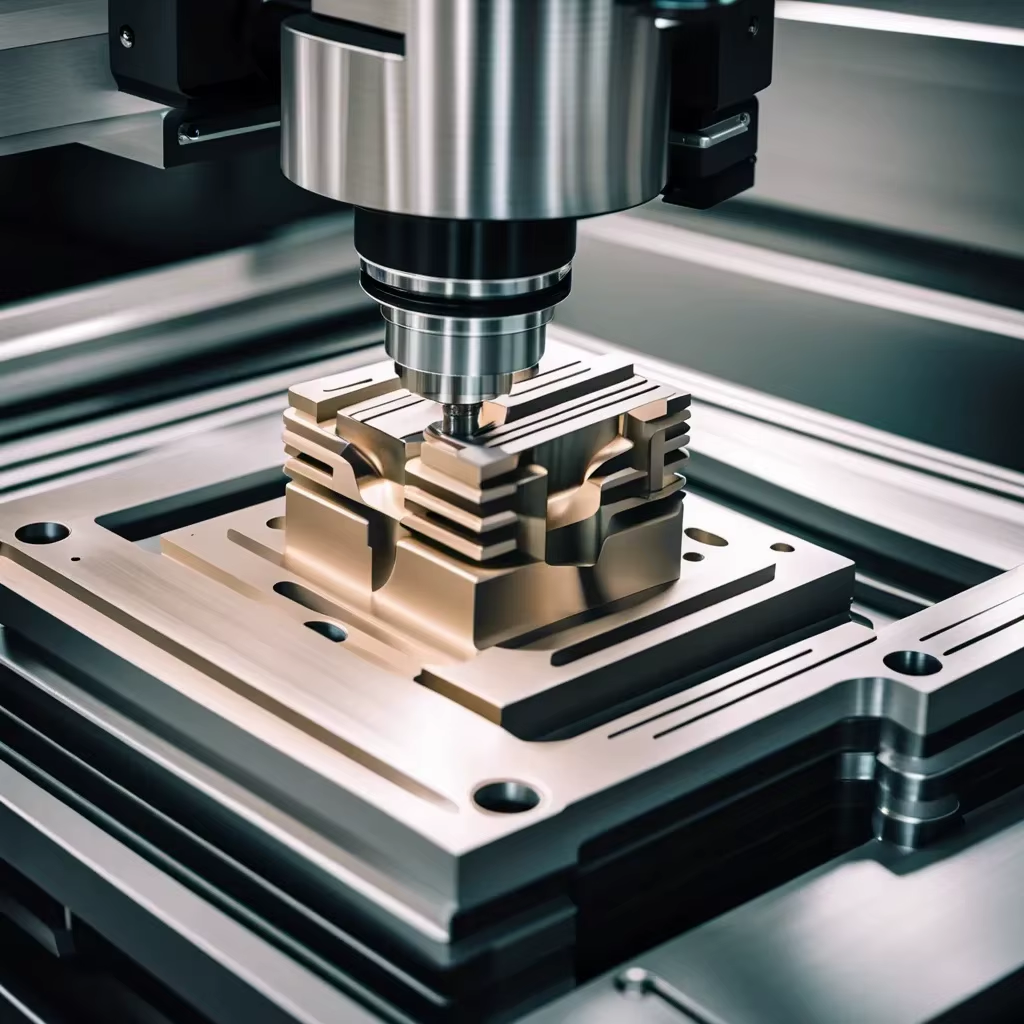
A simultaneous 5-axis machining center moves the tool and the workpiece along five axes at once. The control keeps the tool tip on path while the rotary axes tilt. This is what lets a single setup reach five faces of a prismatic part, or cut a compound angle on a turbine-style profile without a special fixture.
A robot arm is a different kinematic problem. It has more axes, less stiffness and a much smaller stiffness-to-reach ratio. That is why robots rarely cut metal directly in production. They move parts to a machine that is stiff enough to hold ±0.005 mm.
The productive arrangement puts the two together. The robot handles the blank and the finished part, plus deburring or laser marking on a bench. The 5-axis center does the tolerance-critical cutting. Each system works inside its own strength.
Where the boundary sits depends on the part. If the tolerance is looser than about ±0.1 mm, a robot with a spindle can be a reasonable standalone machine. If the callout is ±0.02 mm or tighter, keep the cut in the machining center and use the arm for transport and inspection.
- 1Robot as loaderBest fit when cycle time is dominated by handling
- 2Robot as welderCommon in fabrication cells, not in tight-tolerance milling
- 3Robot as inspectorFeeds a CMM or vision station between operations
Fixtures and datum control decide the outcome
Automation punishes a weak fixture. A machinist can feel a part shift and tap it back. A robot cannot. If the blank sits 0.3 mm off the stop, every part in the run is 0.3 mm off until someone notices.
The fix is a self-locating fixture: a three-point nest, a pull-down clamp, or a hydraulic vise with a fixed jaw that never moves. Locate on a machined surface, not on a casting skin. Castings vary, and the robot has no way to judge that variation.
Datum strategy matters just as much. On a multi-setup part, every re-grip should reference the same feature. A common approach is to cut a small datum pad in operation one, then grip that pad in every later operation. The pad becomes the handshake between the robot and the machine.
Chips are the quiet failure mode. A single chip trapped under a nest leg tilts the part and you lose the whole batch. Air blast before clamping, plus a short probe check on the first part of each pallet, catches most of it.
For parts under 500 mm, a pallet system with repeatable zero-point clamping usually beats a bare robot gripper. The pallet carries the datum; the robot only moves the pallet.
- 1Locate on machined facesCasting skin varies more than any gripper can absorb
- 2Add a probe checkVerify the first part on each pallet before the run continues
When automation pays back and when it does not
The payback math is not about labor rate alone. It is about the ratio of handling time to cutting time. If a part cuts for two minutes and takes six minutes to load, automation can nearly triple output from the same spindle. If a part cuts for three hours, the loading time is noise and the robot mostly buys you unattended nights.
Fixturing cost is the entry ticket. A robot gripper with custom jaws and a locating nest is a real engineering project. On a 50-part order it rarely makes sense. On a 5,000-part order it is usually absorbed in the first weeks.
Low-volume work can still benefit, but for a different reason. If a program runs unattended overnight, the shop starts the next morning with finished parts instead of an empty machine. That shifts delivery from days to overnight without adding a second shift.
The case against automation is real too. Complex organic geometry with many re-grips, parts that flex under clamping, and prototype work that changes every revision are all poor fits. The setup cost gets thrown away when the design moves.
- 1Good fitRepeat geometry, stable fixturing, handling time above 30% of cycle
- 2Poor fitOne-off prototypes, flexible thin walls, frequent design changes
- 3WatchGripper marks on cosmetic surfaces and on soft aluminium
Inspection and traceability in an automated cell
When a machine runs unattended, nobody is watching the first article. That is why automated cells need measurement built into the cycle rather than bolted on at the end. A spindle probe checking a bore every twentieth part catches a worn tool before it scraps a pallet.
Tool life management does the same job from the other side. The control counts cutting time or spindle load and swaps to a sister tool at a set limit. On aluminium at high spindle speed, a drill that has run 20% past its limit will show up as a hole 0.05 mm oversize, not as a broken tool.
Traceability is the part customers ask about. Each pallet can carry a job number, and each part can carry a laser mark. GreatLight uses laser marking with a minimum character height of 1.5 mm so the mark stays readable after anodizing or bead blasting.
Final inspection still happens on a CMM or a vision system. Every part is inspected before shipment, with raw material checks, in-process monitoring and final reports available on request. The robot does not replace that step. It just makes sure the parts arrive at it in the same condition every time.
- 1In-process probeCorrect offsets and flag drift without stopping the run
- 2Tool life limitsSwap at a set time or load limit, not at failure
- 3Marking1.5 mm minimum character height survives most finishes
Process planning steps for a robot cell job
Planning starts with the drawing, not the robot. Read the tolerance stack first. Identify which features need one setup and which can move to a second. Every setup you remove is a fixture you do not have to automate.
Next, pick the locating scheme. Choose three points for the primary datum, two for the secondary, one for the tertiary. Make sure the robot can place the part on that scheme without sliding it. A vertical drop onto a nest is easier to automate than a sideways push into a vise jaw.
Then size the gripper. Aluminum parts under 2 kg are straightforward. Heavier steel parts need a gripper with enough grip force to resist the cutting load if the robot holds the part during the cut. In most cells the machine vise holds the part, and the robot only transfers it.
Finally, define the failure behavior. What happens if the probe reading is out of tolerance? What if the gripper sensor does not confirm closure? A cell that stops and alarms is safe. A cell that keeps running on a bad part is the one that costs money.
- 1Step 1Reduce the number of setups before automating any of them
- 2Step 2Fix the 3-2-1 locating scheme and verify it with a probe
- 3Step 3Size grip force to part weight and cutting load
- 4Step 4Write the alarm and stop logic before the first run
Manual load vs robot cell vs pallet automation
Rough guide for parts under 4,000 mm. Choose by batch size and tolerance, not by novelty.
| Factor | Manual load | Robot cell | Pallet system |
|---|---|---|---|
| Batch size | 1 to 50 parts | 200 to 10,000+ | 50 to 2,000 |
| Setup time per part | 5 to 40 min | Under 1 min | Under 2 min |
| Tolerance floor | ±0.005 mm | ±0.005 mm at the machine | ±0.005 mm at the machine |
| Unattended hours | None | 8 to 16 h per day | Up to 24 h with stacking |
| Part weight limit | Handled by operator | Typically under 20 kg | Up to 500 kg on some pallets |
| Changeover effort | Minutes | New gripper jaws, 1 to 4 h | New pallet fixture, 1 to 3 h |
| Best fit | One-offs, repair work | Repeat runs, simple geometry | Mixed high-mix runs |
Pick the setup that matches the batch
For one-off prototypes and repair work, keep the machine manual. For repeat runs where handling eats more than a third of the cycle, a robot cell pays back. For high-mix work in the hundreds, a pallet system with zero-point clamping usually beats both.
Robot CNC machining questions engineers ask
Can a robot arm hold the part during the cut?
It can, and some cells do it for deburring, polishing and light drilling. The limit is stiffness. A serial arm deflects under cutting force, so the achievable tolerance is usually looser than ±0.1 mm.
For anything tighter, let the machine vise hold the part and use the arm only to move it. That keeps the tolerance at ±0.005 mm on a capable 5-axis center.
Does automation change the surface finish I can get?
No. Finish comes from the tool, the stepover, the spindle speed and the rigidity of the setup. A robot loader does not improve Ra.
What it can do is keep the setup identical across thousands of parts, so the finish does not drift the way it might when a fresh operator re-fixtures the job each shift. Typical achievable ranges are Ra 0.2–0.8 μm for fine finishing and Ra 1.6–3.2 μm as-machined.
What part size and weight fit a robot cell?
Most cells handle parts from a few grams up to roughly 20 kg per grip. Above that, pallet handling or a gantry is the better answer.
On the machine side, GreatLight runs 5-axis centers with travels of 4,000 × 400 × 150 mm, 750 × 1,150 × 550 mm and 600 × 600 × 600 mm, plus a Ø400 mm rotary table. Parts up to 4,000 mm can be processed, though very long parts are usually loaded by hand or gantry.
Which materials cause problems in an automated cell?
Soft aluminium grades such as 6061 and 5052 mark easily, so gripper jaws need a plastic or urethane pad. Castings and forgings vary in size, which makes blind nesting risky.
Titanium and Inconel cut slowly and generate heat, so unattended runs need solid tool life limits. Plastics like POM and PEEK machine cleanly but hold chips and burrs, so an air blast between cycles matters.
How do I know the cell is producing good parts at 3 a.m.?
You do not, unless the cell measures. Build in a probe check on a known feature every ten to twenty parts, and log the readings. A trend in the log tells you a tool is wearing before the parts go out of tolerance.
Pair that with tool life limits and a hard stop on any out-of-tolerance reading. A cell that alarms is cheaper than a cell that ships scrap.
What do I need to send for an automated-run quote?
Send the 3D model, the 2D drawing with tolerances and finish callouts, the material, and the annual or batch quantity. Quantity drives whether automation is worth quoting at all.
Uploads are secure and confidential, and an NDA is available on request. Quotation and a free DFM analysis come back within 12 hours.
Send the drawing, get a process plan
Upload your model and tolerances. We review the setups, the fixturing and the batch size, then quote the route that fits.
12-hour quote±0.005 mm toleranceNo minimum order quantity100% inspection
More process notes
We publish setup notes, tooling trials and inspection data from the factory floor.











